

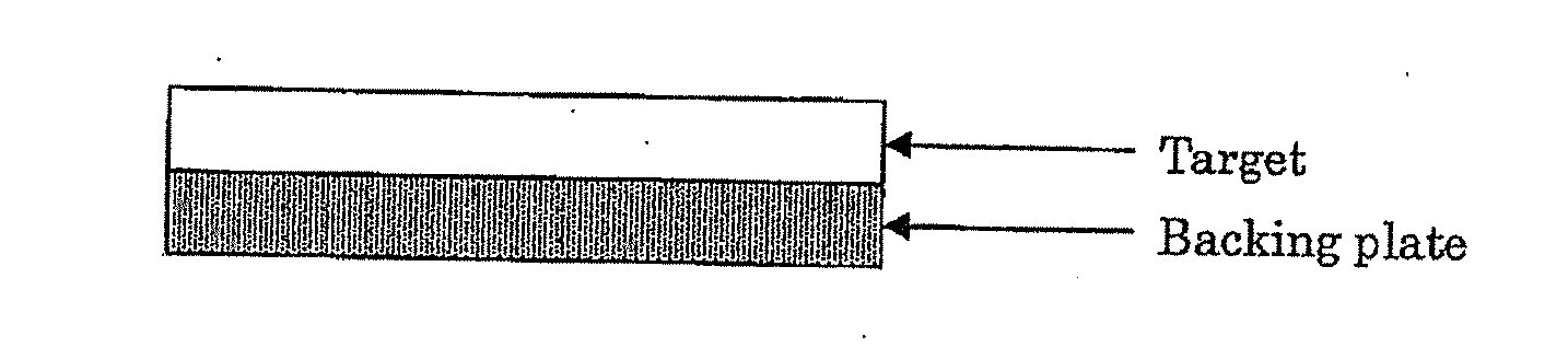
Sputtering target-backing plate assembly
a technology of backing plate and sputtering, which is applied in the direction of diaphragms, metal layered products, metallic material coating processes, etc., can solve the problems of debonding, affecting production costs, and defects of an increase in the number of steps and cost, and achieves stable sputtering, high quality, and high average pass through flux
- Summary
- Abstract
- Description
- Claims
- Application Information
AI Technical Summary
Benefits of technology
Problems solved by technology
Method used
Image

Examples
example 1
[0077]For a powder mixture for magnetic material target, prepared were a Co powder having an average particle diameter of 1 μm, a Cr powder having an average particle diameter of 2 μm, a Pt powder having an average particle diameter of 2 μm, a SiO2 powder having an average particle diameter of 1 μm, and a CoO powder having an average particle diameter of 3 μm. The raw material powders were mixed at a composition of Co-17Cr-15Pt-5SiO2-8CoO (mol %) with a mixer.
[0078]Separately, for a backing plate, similarly prepared were a Co powder having an average particle diameter of 1 μm, a Cr powder having an average particle diameter of 2 μm, and a SiO2 powder having an average particle diameter of 1 μm (the particle diameters of these powders have no importance and are therefore not shown, and surplus powders for the target can be used. The same shall apply hereinafter). These powders were mixed at a composition of Co-25Cr-9SiO2 (mol %), hot-pressed and subjected to machining to prepare a ba...
example 2
[0088]As in Example 1, for a powder for a magnetic material target, prepared were a Co powder having an average particle diameter of 1 μm, a Cr powder having an average particle diameter of 2 μm, a Pt powder having an average particle diameter of 2 μm, a SiO2 powder having an average particle diameter of 1 μm, and a CoO powder having an average particle diameter of 3 μm, and these powders were mixed at a target composition of Co-17Cr-15Pt-5SiO2-8CoO (mol %) with a mixer.
[0089]Separately, for a backing plate, similarly prepared were a Co powder, a Cr powder, and a SiO2 powder. These powders were mixed at a composition of Co-25Cr-9SiO2 (mol %), hot-pressed and subjected to machining to prepare a backing plate.
[0090]The magnetic permeability of this backing plate measured with a B-H meter (analyzer) was 1.0. The magnetic permeability of the target was significantly higher than this value.
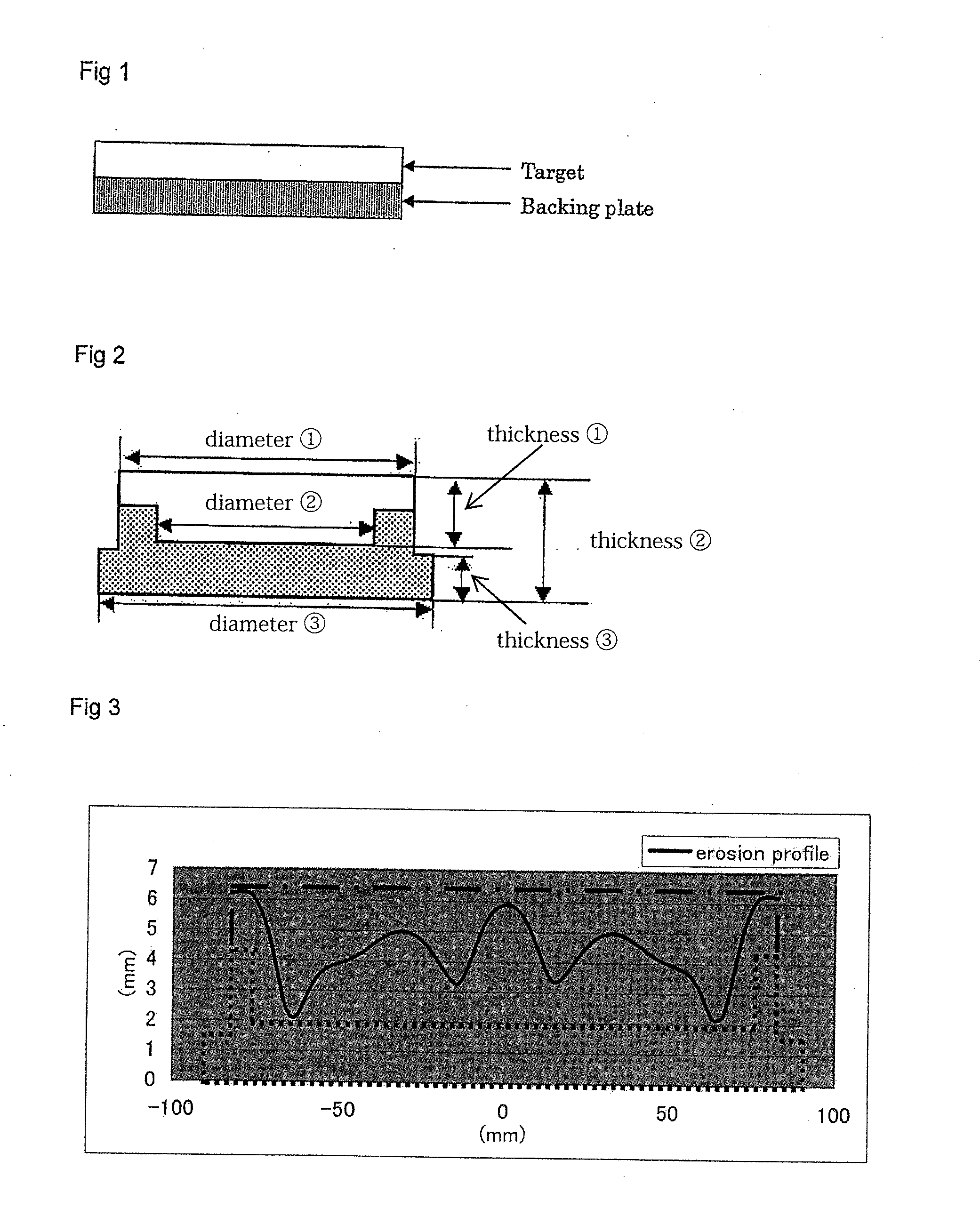
[0091]The backing plate was machined to have an ashtray-like shape (in another word, tub-shape) hav...
example 3
[0094]For a raw material powder for a magnetic material target, prepared were a Co powder having an average particle diameter of 1 μm, a Cr powder having an average particle diameter of 2 μm, a Pt powder having an average particle diameter of 2 μm, a Ru powder having an average particle diameter of 3 μm, a TiO2 powder having an average particle diameter of 1 μm, and a CoO powder having an average particle diameter of 3 μm, and these powders were mixed at a composition of Co-15Cr-18Pt-5Ru-4TiO2-8CoO (mol %) with a mixer.
[0095]Separately, for a backing plate, similarly prepared were a Co powder, a Cr powder, and a SiO2 powder. These powders were mixed at a composition of Co-25Cr-10SiO2 (mol %), hot-pressed and subjected to machining to prepare a backing plate material.
[0096]The magnetic permeability of this backing plate measured with a B-H meter (analyzer) was 1.0. The magnetic permeability of the target was significantly higher than this value.
[0097]And the backing plate material wa...
PUM
| Property | Measurement | Unit |
|---|---|---|
| temperature | aaaaa | aaaaa |
| pressure | aaaaa | aaaaa |
| temperature | aaaaa | aaaaa |
Abstract
Description
Claims
Application Information