Display calibration system and storage medium

a calibration system and display technology, applied in the field of display calibration systems, can solve problems such as differences in gamma characteristic and output color, and obtain unsatisfactory gamma characteristic of liquid crystal panels, and achieve the effect of maintaining the accuracy of the calibration process in an acceptable level and processing tim

Active Publication Date: 2015-07-30
SHARP KK
View PDF8 Cites 16 Cited by
  • Summary
  • Abstract
  • Description
  • Claims
  • Application Information

AI Technical Summary

Benefits of technology

[0017]A display calibration system in accordance with an aspect of the present invention yields the effect of enabling a processing time required for the calibration process to be shorter than ever before while maintaining accuracy of the calibration process in an acceptable level.

Problems solved by technology

This can cause deviation of the optical transmittance of the liquid crystal panel from its design value, with the result that an unsatisfactory gamma characteristic (display non-uniformity) of the liquid crystal panel is obtained.
Meanwhile, the above large screen display system can have the problem of differences in gamma characteristic and output color between the displays provided therein, due to non-uniform display characteristics of the displays.

Method used


Image

  • Display calibration system and storage medium
  • Display calibration system and storage medium
  • Display calibration system and storage medium

Examples


embodiment 1

[0051]The following will describe an embodiment of the present invention with reference to the drawings. First, the configuration of a display calibration system in accordance with the present embodiment will be described.

[0052](Configuration of Display Calibration System)

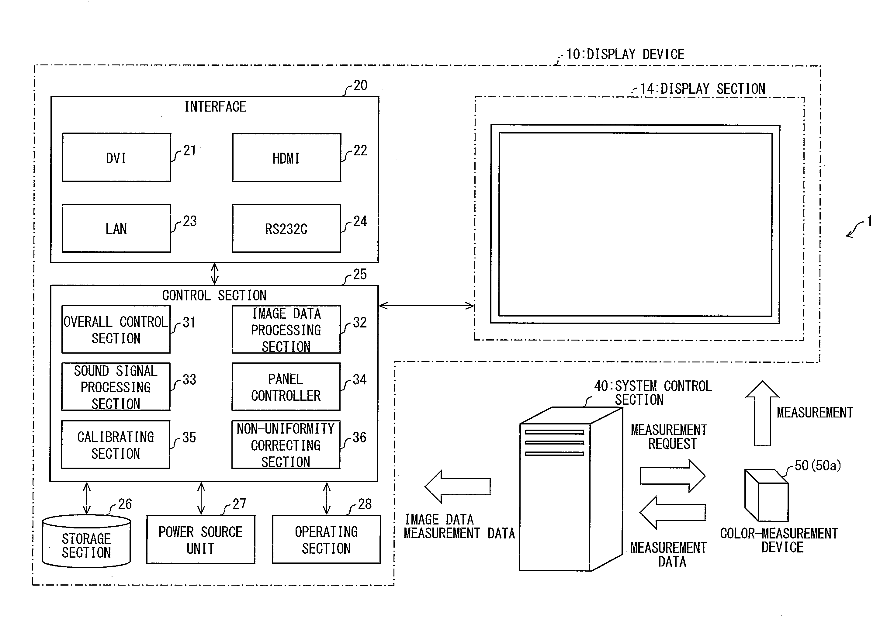
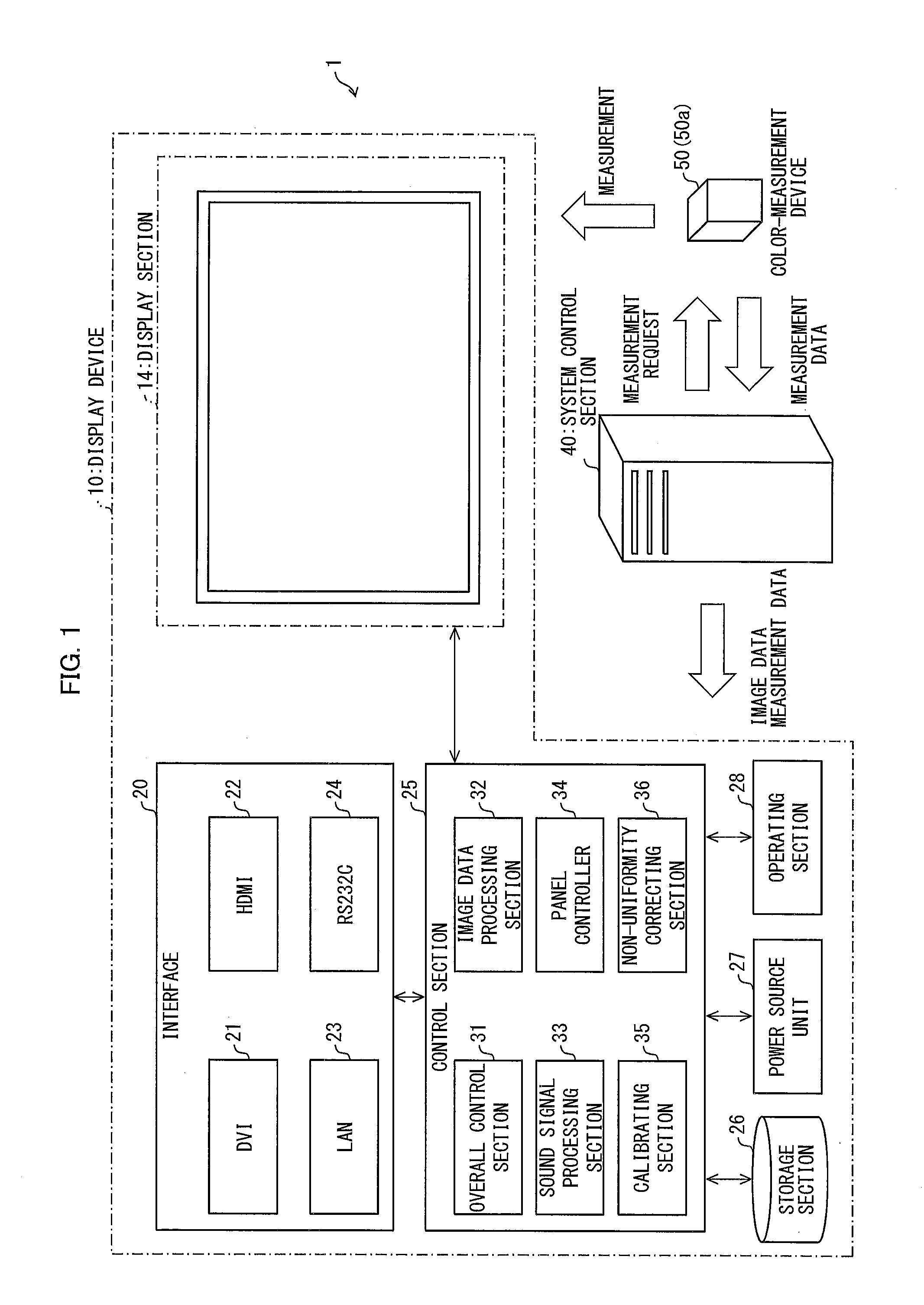
[0053]As illustrated in FIG. 1, a display calibration system 1 in accordance with the present embodiment includes a display device 10, a system control section (computer) 40, and a measuring section 50. The display device 10 includes an interface 20, a control section (signal processing section) 25, a storage section 26, a power source unit 27, an operating section 28, and a display section 14.

[0054]The interface 20 includes: a DVI (Digital Visual Interface) terminal 21 and a HDMI® (High-Definition Multimedia Interface) terminal 22, both of which are used for serial communications based on TMDS (Transition Minimized Differential Signaling); a LAN terminal 23 and a RS232C terminal 24; both of which are used for comm...

embodiment 2

[0182]Although not frequently, correction performed by the method described in Embodiment 1 can cause the following problem. That is, Embodiment 1 has described the arrangement in which the pieces of adjustment value information (see FIG. 11) for the individual pixels are divided into groups by the clustering process. In this arrangement, in a case where there is a large variability among the magnitudes of the adjustment values contained in one (1) piece of adjustment value information, an adjustment value applied to a certain piece of color information (R, G, B) can deviate greatly from a proper adjustment value as intended, depending upon a pixel.

[0183]This is caused under a situation, for example, such that in a case where there is a large variability among the magnitudes of the adjustment values contained in the adjustment value information, Euclidean distance between first adjustment value information and second adjustment value information is short although an adjustment value...

embodiment 3

[0213]Embodiment 3 is a modification example of Embodiment 2. In Embodiment 2, the first-stage correction (coarse adjustment) is performed with use of the representative value table illustrated in FIG. 18A, after which the fine adjustment (second-stage correction) is performed with use of the non-uniformity correction map and index map generated by the clustering process. However, even when the fine adjustment is omitted, pixel non-uniformity can be suppressed up to a point as long as the coarse adjustment is performed. Hence, an arrangement in which the coarse adjustment is performed alone without the fine adjustment may be adopted alternatively. In Embodiment 3, such an arrangement will be described.

[0214]In Embodiment 3, the map outputting section 45a is omitted in FIG. 22, and a representative value table generating section is provided instead. The representative value table generating section is a block configured to perform processing that is the same as the processing perform...


PUM


Abstract

A display calibration system includes: a display section subject to calibration; a correction data outputting section configured to perform a calibration process to determine, for each of the pixels of the display section, correction data for non-uniformity correction; and a first storage section configured to store reference data to be used in the calibration process. The reference data represents, for individual color patches of a first predetermined number, correspondences between RGB values and reference values. The correction data outputting section obtains, on a basis of the reference data and the measurement values of the color patches of a second predetermined number that is less than the first predetermined number, the pieces of correction data with respect to RGB values of the individual color patches of the predetermined second number. With this arrangement, it is possible to shorten a processing time of the calibration process.

Description

[0001]This nonprovisional application claims priority under 35 U.S.C. §119 on Patent Application No. 2014-016031 filed in Japan on Jan. 30, 2014, the entire contents of which is hereby incorporated by reference.TECHNICAL FIELD[0002]The present invention relates to a display calibration system, a display calibration method, and a storage medium all of which implements a calibration process (calibration) for correcting display non-uniformity of a display device(s).BACKGROUND ART[0003]In recent years, a display device with a large screen has been used for a wide variety of applications, such as a signage and an information display. With this trend, there have been increasingly developed a single display providing a large screen display and a large-screen display system including multiple displays in which a plurality of displays are arranged in a matrix manner.[0004]A liquid crystal panel display includes: a liquid crystal panel including two glass substrates between which a liquid cry...

Claims


Application Information

Patent Timeline
Patent Type & Authority Applications(United States)
IPC IPC(8): G09G3/36G01J3/46
CPCG09G3/3607G01J3/46G09G2340/06G09G2320/0666G09G2320/0693G09G3/006G09G3/3648G09G2300/04G09G2320/0285G09G2320/0673G01J3/462G01J3/506
Inventor OHNISHI, HIDEKIKATOUGI, TERUMITSUHAYASAKI, MAKOTOFURUICHI, GAKUADACHI, YASUSHI
Owner SHARP KK
Why Eureka
Try Eureka