Methods and devices for smoking urge relief

a technology of urge relief and methods, applied in the direction of ict adaptation, tobacco, respirator, etc., can solve the problems of lapse, eventual relapse, and ineffectiveness of current nicotine replacement therapies (nrts), so as to reduce the urge, and reduce the urge to smoke

Inactive Publication Date: 2015-08-06
FONTEM HLDG 1
View PDF5 Cites 173 Cited by
  • Summary
  • Abstract
  • Description
  • Claims
  • Application Information

AI Technical Summary

Benefits of technology

[0014]In one aspect, provided herein is a method of treating a subject with an urge to smoke comprising administering to the subject a therapeutically effective amount of a condensation aerosol comprising nicotine, wherein the administering comprises the subject inhaling the condensation aerosol comprising nicotine from a device configured to generate the condensation aerosol comprising nicotine from a liquid formulation comprising nicotine, and wherein the administering generates a nicotine plasma concentration in the subject of from about 0.5 ng/ml to 1 ng/ml, thereby reducing the urge to smoke in the subject. In some cases, the therapeutically effective amount is from about 500 μg to about 1000 μg. In some cases, the therapeutically effective amount is about 500 μg. In some cases, the therapeutically effective amount is about 1000 μg. In some cases, the subject inhales the condensation aerosol comprising nicotine a plurality of times in order to deliver the therapeutically effective amount. In some cases, the plurality of times is from about 2 to about 10 inhalations. In some cases, the subject administers the condensation aerosol on demand. In some cases, the subject administers the condensation aerosol multiple times per day. In some cases, the reduction in the urge to smoke in the subject is at least 50%. In some cases, the reduction in the urge to smoke in the subject is at least 60%. In some cases, the reduction in the urge to smoke in the subject is at least 70%. In some cases, the reduction in the urge to smoke in the subject is at least 80%. In some cases, the reduction in the urge to smoke in the subject is a complete or substantially complete elimination of the urge to smoke in the subject. In some cases, the reduction in the urge to smoke is compared to an urge to smoke in the subject before using the aerosol generating device. In some cases, the reduction in the

Problems solved by technology

Current nicotine replacement therapies (NRTs) are not effective for approximately 85% of users.
In some cases, existing NRTs and electronic cigarettes (eCigs) fail to provide sufficient doses of nicotine.
Many smokers using NRTs under-dose, resulting in break-through cravings, which can lead to smoking lapses and eventual relapse.
Deep lung absorption of nicotine can facilitate rapid delivery of nicotine to the brain, which can result in a subsequent cessation of nicotine cravings.
A typical electronic cigare

Method used


Image

  • Methods and devices for smoking urge relief
  • Methods and devices for smoking urge relief
  • Methods and devices for smoking urge relief

Examples


example 1

Effect of Changes in Air Flow Rate, Electrical Current, Duration of Heating, and Thickness of Heater Element on Particle Size of a Aerosol Generated from a Propylene Glycol Formulation

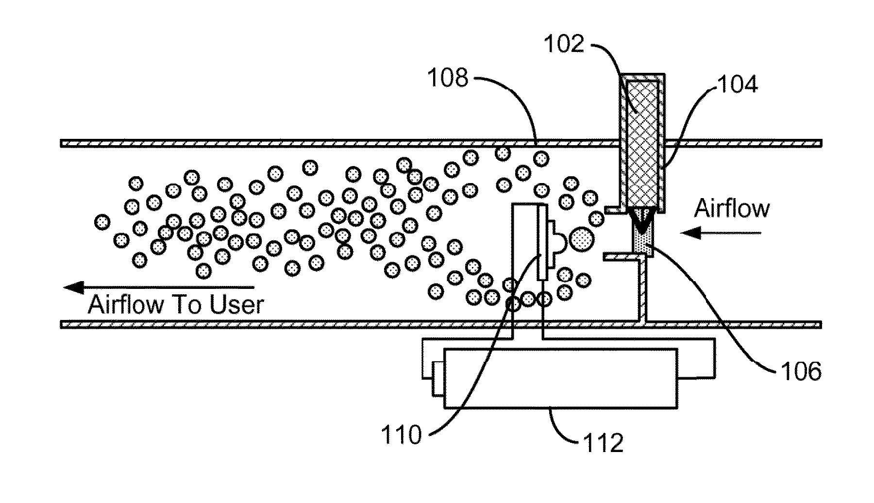
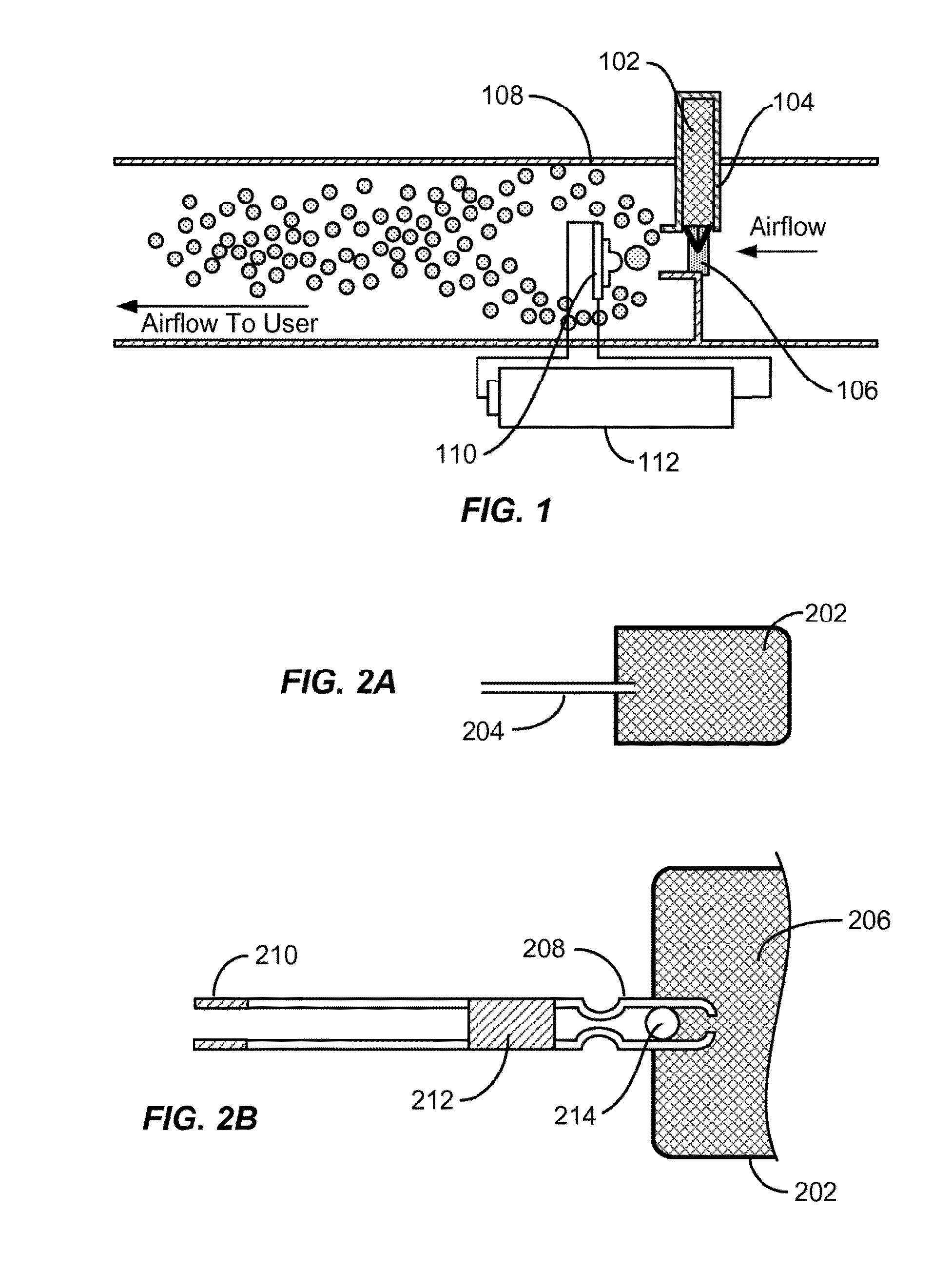
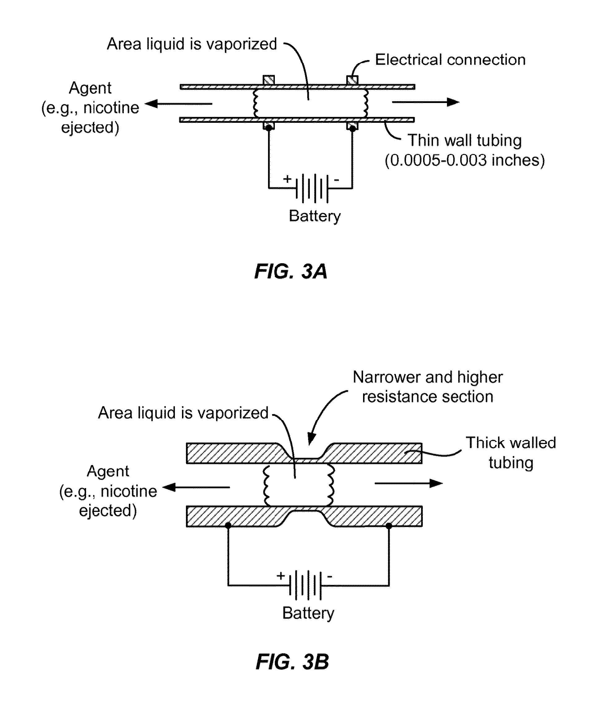
[0422]This example describes how changes in specific parameters (i.e. air flow rate, electrical current to a heater element, and thickness of a heater element) affected the size of aerosol particles generated by a test apparatus designed to comprise components and / or parameters of a nicotine delivery device as described herein. FIG. 26 shows a schematic of the entire test apparatus while FIGS. 27A-D shows alternate views of the test airway used in the test apparatus. The test bed had an airway created between a block of Delrin (bottom) and a sheet of clear plexiglass (top) with brass sides used to clamp and make electrical contact with a heater element. The heater element was a stainless steel foil of variable thickness (0.0005 inches (about 0.013 mm) or 0.001 inches (about 0.025 mm)), and the formulat...

example 2

Effect of Changes in Air Flow Rate, Electrical Current, Duration of Heating, and Thickness of Heater Element on Particle Size of an Aerosol Generated from a Nicotine / Propylene Glycol Formulation

[0423]This example describes how changes in specific parameters (i.e. air flow rate, and electrical current to a heater element) affected the size of aerosol particles generated from a 10% nicotine / propylene glycol formulation by a test apparatus as described in Example 1. Table 3 shows the results of altering heater element thickness, air flow rate, current, and duration of heating on particle size distribution. As shown in Table 3, when air flow rate was altered while other parameters were held constant, the higher the air flow rate, the smaller the average particle size diameter (PSD).

TABLE 3Nicotine / propylene glycol mixture (10%) aerosol data from test airwayHeater ElementAir FlowDurationAverage ParticleThicknessRateDoseCurrentof HeatingSize DiameterSequenceMaterial(inches)(Liters / min)(mg...

example 3

Particle Size Diameter Ranges of Aerosols Generated from a Test Apparatus Using a Heater Element Comprising a Wire Coil

[0424]This example describes the particle size diameters of aerosols generated from either a PG formulation or 10% nicotine / PG formulation using a test apparatus as shown in FIGS. 26 and 27A-D and described in Example 1. In this example, the heater element was a stainless steel coil comprising 3.5 coils and a diameter of 0.10 inches (about 2.54 mm). The heater element was heated using a current of 2.5 Amps and the air flow rate was 4 Liters / min (about 6.7×10⁻⁵ m3 / s). Table 4 shows the results.

TABLE 4Air FlowParticleRateDurationSize(Liters / DoseCurrentof HeatingDiameterSequenceMaterialmin)(mg)(Amps)(seconds)(microns)1PG412.511.5-2.22PG412.511.5-2.23Nic / PG412.511.57-2.2 4Nic / PG212.511.6-2.85Nic / PG212.511.52-2.2 6PG212.511.5-2.27PG412.511.5-2.38PG412.512.4-1.5


PUM


Abstract

Provided herein are methods, devices, systems, and computer readable medium for delivering one or more compounds to a subject. Also described herein are methods, devices, systems, and computer readable medium for transitioning a smoker to an electronic nicotine delivery device and for smoking or nicotine urge relief.

Description

CROSS-REFERENCE[0001]This application claims the benefit of U.S. Provisional Application Nos. 61 / 977,591, filed on Apr. 9, 2014, 61 / 971,456, filed on Mar. 27, 2014, 61 / 950,775, filed on Mar. 10, 2014, 61 / 949,771, filed on Mar. 7, 2014, 61 / 937,313, filed on Feb. 7, 2014, and 61 / 930,391, filed on Jan. 22, 2014, each of which is herein incorporated by reference in its entirety.BACKGROUND[0002]There is a need for new methods and devices for administering compounds, such as pharmaceutical agents, to a subject. In particular, there is a need for methods and devices for delivery of compounds to a subject where the compounds are aerosolized to fall within a specified particle size range. In some cases, particles within a specified size range can be efficiently delivered to the deep lung. For example, there is an urgent need for improved methods and devices to deliver nicotine to a subject in specified doses and in a specified particle range size without the carcinogens and other chemicals a...

Claims


Application Information

Patent Timeline
IPC IPC(8): A24F47/00H05B1/02A24F40/10A24F40/48A24F40/50
CPCH05B1/0244A24F47/008A24F40/48A24F40/10A24F40/46A61M11/042A61M15/06A61M2205/3584A61M2205/52A61M2205/3592A61M2205/0211A61M2205/8206A61M11/002A61M15/0036A61M2205/3334A61M11/001A61M15/0083A61M2206/10A61M2205/3653A61M2016/0024A61M2205/3306A61M15/002A61M15/0015A61M2205/0238A61M2016/0021A61M2205/581A61M2016/0033A61M15/008A61M2206/18A61M15/0066A61M2205/3553A61M2205/502A61M2205/583A61M2209/02A61M15/0025G16H20/13A24F40/50Y02A90/10
Inventor WENSLEY, MARTINHUFFORD, MICHAELWILLIAMS, JEFFREYLLOYD, PETER
Owner FONTEM HLDG 1
Why Eureka
Try Eureka