System for automated adjustment of a pressure set by a ventilation device

a technology of automatic adjustment and ventilation device, which is applied in the direction of valve operating means/releasing devices, applications, diagnostic recording/measuring, etc., can solve the problems of reduced oxygen saturation, severe impairment of the functional residual capacity of the lungs, and collapse of alveoli

Active Publication Date: 2015-08-06
HAMILTON MEDICAL AG
View PDF1 Cites 18 Cited by
  • Summary
  • Abstract
  • Description
  • Claims
  • Application Information

AI Technical Summary

Benefits of technology

[0021]A brief occlusion of the type described can be brought about in simple manner, when both an airway inlet valve and an airway outlet valve of the ventilation device are closed for a predetermined occlusion period. Both valves are present anyway and only need to be controlled in correspondingly synchronous manner.
[0025]In order to avoid too frequent changes in PEEP and / or maximum airway pressure, the PEEP and / or the maximum airway pressure may not only be determined on the basis of the current breathing cycle, but it is also possible to make use of the values of the PEEP and / or the maximum airway pressure determined in several preceding breathing cycles. It is thus possible to compensate for measurement inaccuracies or static fluctuations, so that the PEEP and / or the maximum airway pressure is not readjusted before the physiological condition of the patient shows an actual trend. A similar effect can be achieved by an additional or alternative comparison of the PEEP and / or maximum airway pressure determined for the subsequent breathing cycle with the PEEP and / or maximum airway pressure set for the current breathing cycle, with the proviso that the PEEP and / or the maximum airway pressure is changed only if the difference between the two values exceeds a predetermined threshold value.

Problems solved by technology

This kind of positive pressure ventilation may under certain circumstances have the effect that the pressure conditions in the respiratory tract and in the alveoli, respectively, at the end of the expiration phase become so unfavorable that there is a collapse of parts of the alveoli.
The functional residual capacity of the lungs is severely compromised, so that the oxygen saturation decreases, and also the lung tissue is permanently damaged.
On the other hand, a too high value of the PEEP may have negative effects, especially during the inspiration phase.
Moreover, numerous studies also point out that a high value of PEEP may impede the return flow of venous blood to the heart, with corresponding negative effects on the cardiovascular system.
The transpulmonary pressure in a ventilated patient, however, is not amenable to simple definition.
Such guidelines naturally are not suited to reflect the actual state of a patient, but merely give experience values.
For example, it is assumed that in patients with relatively stiff chest, a PEEP set in accordance with the ARDSnet Guidelines will often be too low, with the result that the ventilated patient is not adequately oxygenated, not even if the PEEP is adjusted in accordance with the predetermined guidelines.
A major disadvantage of known methods of deriving an optimal PEEP for a particular patient is that the necessary measurement procedures take considerable time during which patient ventilation is not possible in a regular breathing cycle.
The possibility of an automatic adjustment of the PEEP by the ventilation device is thus indeed given in principle, but cannot be utilized satisfactorily in practice.

Method used


Image

  • System for automated adjustment of a pressure set by a ventilation device
  • System for automated adjustment of a pressure set by a ventilation device
  • System for automated adjustment of a pressure set by a ventilation device

Examples


Embodiment Construction

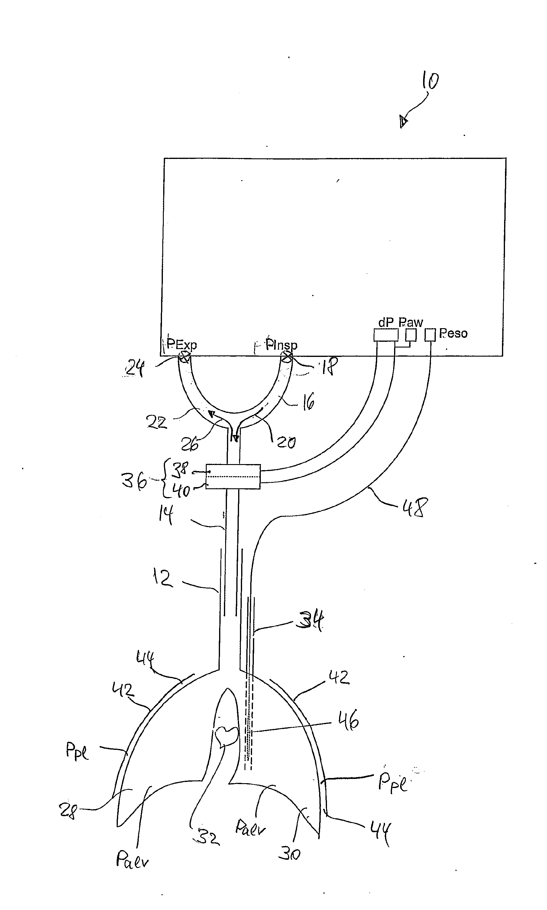
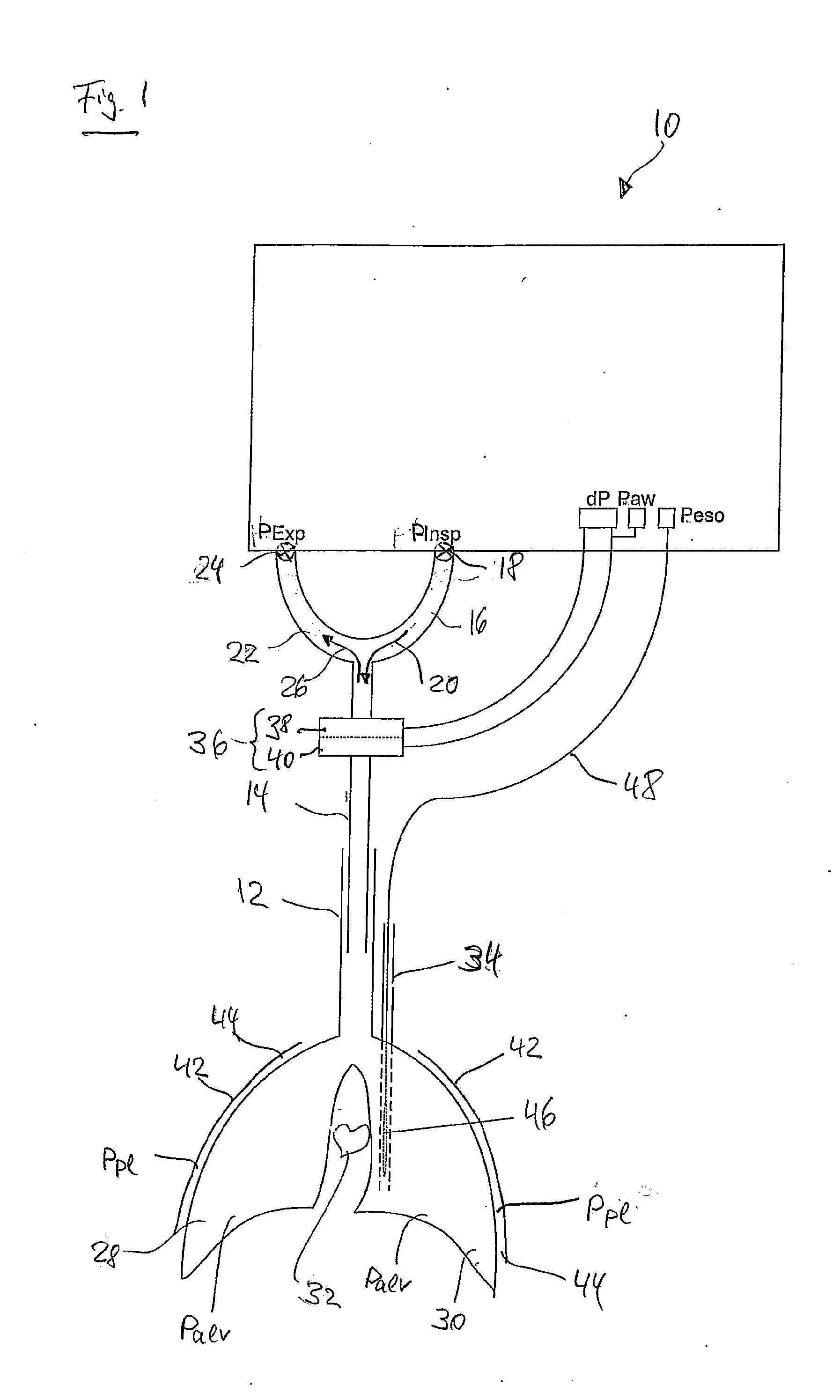
[0055]FIG. 1 shows the essential elements of a ventilation device 10 in a highly schematic representation and in the form of a block diagram. The ventilation device 10 is shown in FIG. 1 in a state with intubated windpipe (trachea) 12 of a ventilated patient. In addition to the trachea 12, FIG. 1 very schematically illustrates the lung lobes 28, 30, the heart 32, the gullet (esophagus) 34 and the chest wall 42 of the patient. The tube 14 of the ventilation device 10 is pushed a certain distance into the trachea 12, usually via the mouth opening (not shown) of the patient, in order to supply breathing gas to the airway. Exhaled air is discharged via the tube 14 as well, which branches at its upstream end into a first end 16 and a second end 22. The first end 16 is connected via an airway inlet valve 18 to an airway inlet connector of the ventilation device 10 for applying an inspiration pressure PInsp. In the open position of the airway inlet valve 18, the inspiration pressure PInsp ...


PUM


Abstract

The invention suggests a system for automated adjustment of a pressure set by a ventilation device, in particular a positive and-expiratory pressure and / or a maximum airway pressure, the system comprising a pressure detection arrangement for detecting a transpulmonary pressure at the end of an expiration phase and / or for detecting a transpulmonary pressure at the end of an inspiration phase, and a means for automated adjustment of the pressure set by the ventilation device on the basis of the transpulmonary pressure detected at the end of the expiration phase and / or the transpulmonary pressure detected at the end of the inspiration phase.

Description

BACKGROUND[0001]1. Technical Field[0002]The present invention relates to a system for the automated adjustment of a pressure specified or set by a ventilation device, in particular a positive end-expiratory pressure and / or a maximum airway pressure. The invention also relates to a device for machine ventilation that is provided with such a system for adjusting the set pressure, in particular the positive end-expiratory pressure and / or the maximum airway pressure.[0003]2. Description of the Related Art[0004]In today's common forms of machine ventilation, breathing gas is supplied to the patient at a positive pressure. This is why the airway pressure or the alveolar pressure during ventilation is greater than the pressure in the pleural gap surrounding the pulmonary alveoli at least during the inspiration phase. During the expiration phase, there is no pressure applied to the airway by the ventilation device, with the result that the lung tissue relaxes and the airway pressure or alve...

Claims


Application Information

Patent Timeline
Patent Type & Authority Applications(United States)
IPC IPC(8): A61M16/00A61M16/20
CPCA61B5/08A61B5/085A61M16/0051A61M2016/0027A61M2205/3331A61M2205/502A61M16/0003A61M16/0069A61M16/20A61M2016/0036A61M16/024A61M2210/105A61B5/037
Inventor NOVOTNI, DOMINIKLAUBSCHER, THOMAS
Owner HAMILTON MEDICAL AG
Why Eureka
Try Eureka