Mixed flow turbine

a flow turbine and mixed technology, applied in the direction of machines/engines, stators, liquid fuel engines, etc., can solve the problems of increasing weight and inertial mass, “decreasing rotational acceleration”, etc., to improve the characteristic of impulse blade turbines, improve the transient response, and increase the velocity of inflow

Active Publication Date: 2015-08-06
MITSUBISHI HEAVY IND LTD
View PDF1 Cites 11 Cited by
  • Summary
  • Abstract
  • Description
  • Claims
  • Application Information

AI Technical Summary

Benefits of technology

[0023]That is, the shroud-side flow has a high degree of reaction, and the flow velocity inside the rotor blade can be reduced and the friction loss can be reduced, thereby providing a so-called “reaction turbine” characteristic, which realizes a high-efficiency flow.
[0067]According to the present invention, there is provided a mixed flow turbine, wherein a front edge, through which a fluid flows in, is shaped so that a middle portion thereof between a hub side and a shroud side is formed so as to protrude toward an upstream side past a line extending between the hub side and the shroud side, and a shroud-side inflow passageway and a hub-side inflow passageway are formed by a scroll partition wall; intermediate blades having an intermediate height are provided between main blades in a hub-side portion of a turbine rotor blade exerting an impulse blade turbine characteristic, thus improving the impulse blade turbine characteristic and reducing the moment of inertia for the rotor blade as a whole, thereby improving the efficiency and improving the transient response.

Problems solved by technology

Generally, in order to “improve the efficiency aerodynamically”, it is an effective approach, for example, to increase the number of blades to reduce the blade load, but it will increase the weight and increase the inertial mass, on the other hand, thereby resulting in a problem of a “decrease in the rotational acceleration”, and therefore there has been a demand for an approach capable of realizing both of these contradicting effects.

Method used


Image

  • Mixed flow turbine
  • Mixed flow turbine
  • Mixed flow turbine

Examples


first embodiment

[0088]A first embodiment of the present invention will now be described with reference to FIGS. 1 and 2.

[0089]A mixed flow turbine 1 of the present invention will be described in examples for use in superchargers (turbochargers) of vehicle engines.

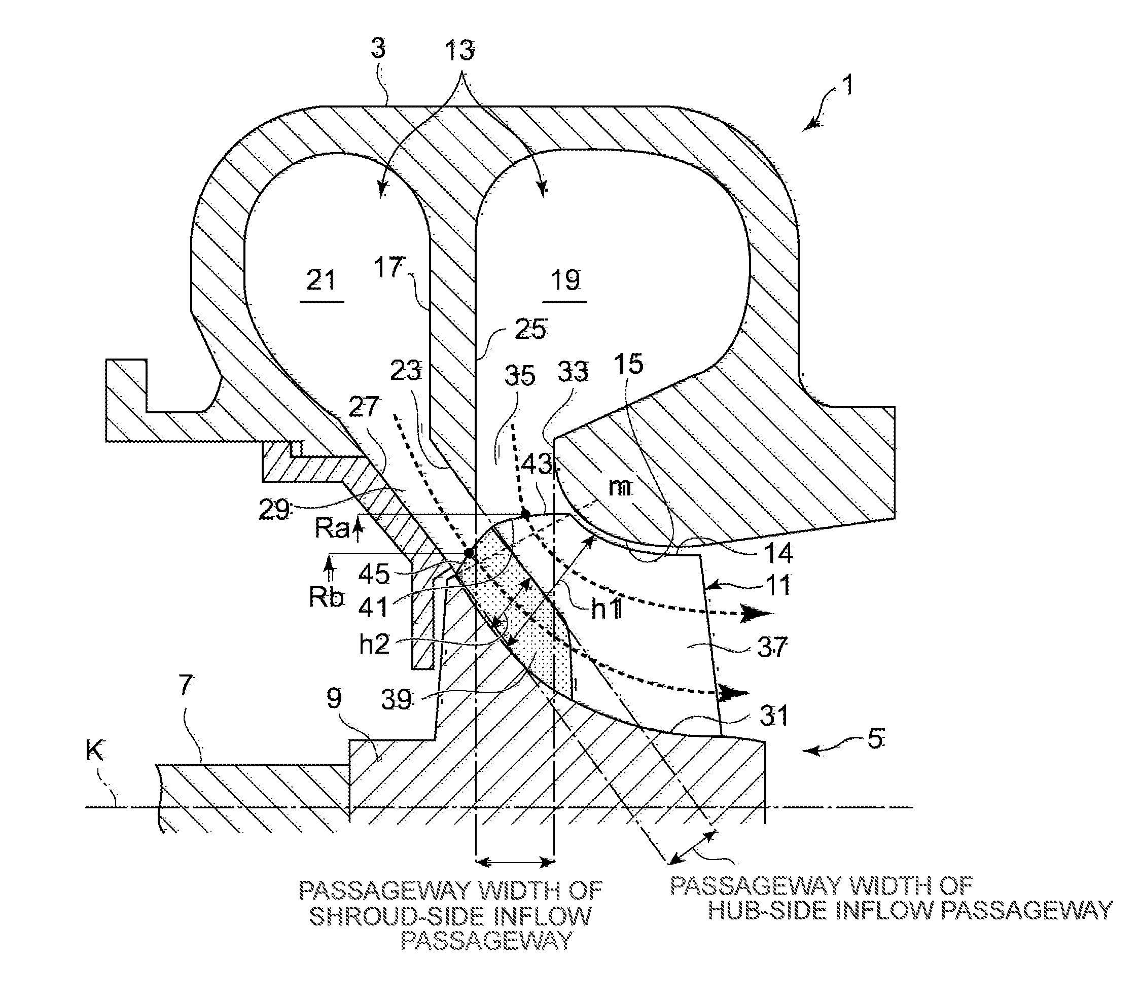
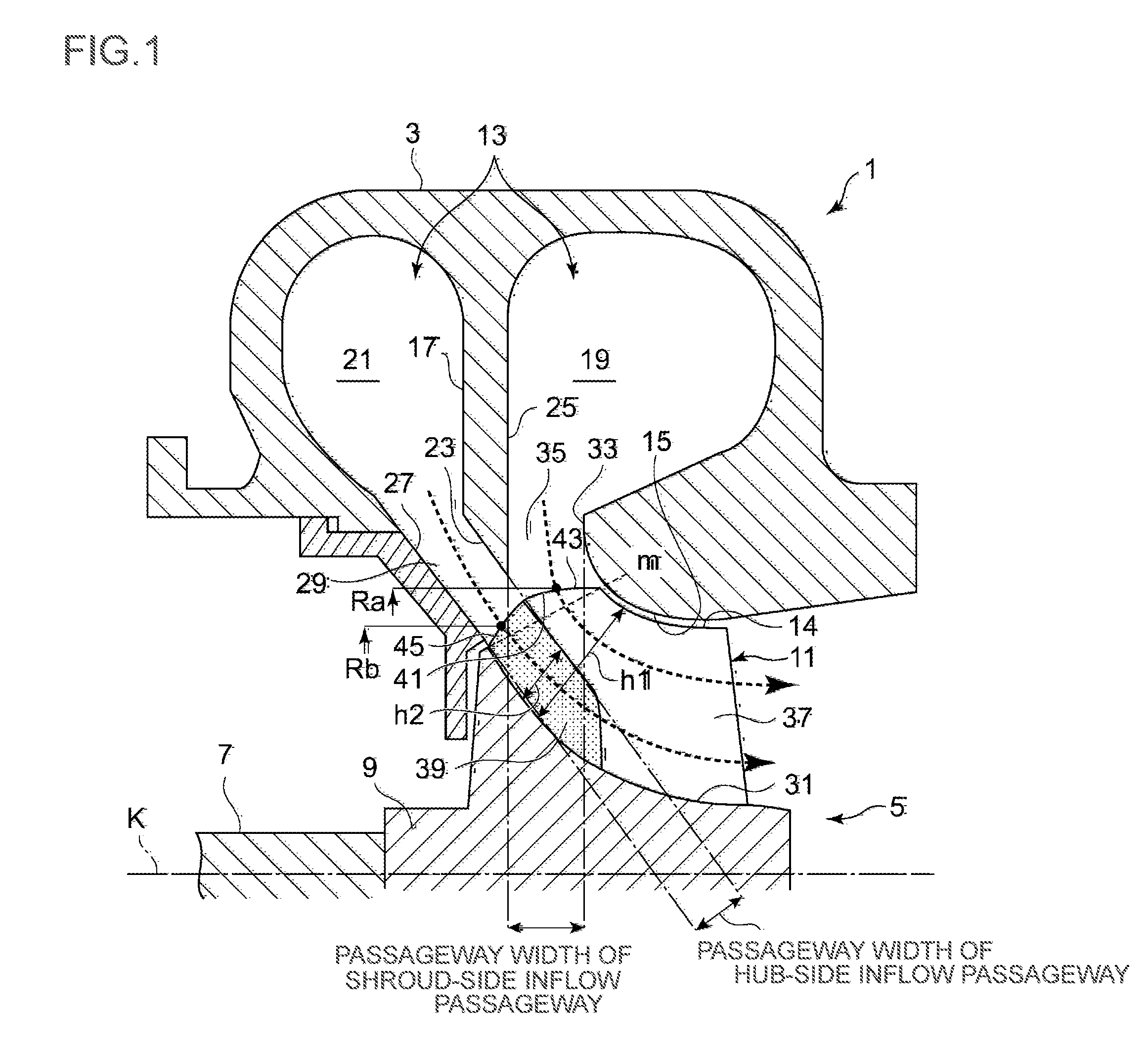
[0090]In FIG. 1, the mixed flow turbine 1 includes a turbine housing 3, and a turbine wheel 5 rotatably supported and accommodated in the turbine housing 3. The turbine wheel 5 includes a rotating shaft 7, a hub 9 integral or welded with the rotating shaft 7, a turbine rotor blade (rotor blade) 11 provided standing on the outer circumferential surface of the hub 9, wherein a snail-shaped scroll chamber (scroll portion) 13 formed in the turbine housing 3 creates a swirl flow having a velocity around the central axis K of the rotating shaft 7, and the swirl flow swirls on the outer circumferential side of the turbine wheel 5.

[0091]The rotating shaft 7 is supported in a bearing housing with a bearing (not shown). The turbine wheel 5 is attach...

second embodiment

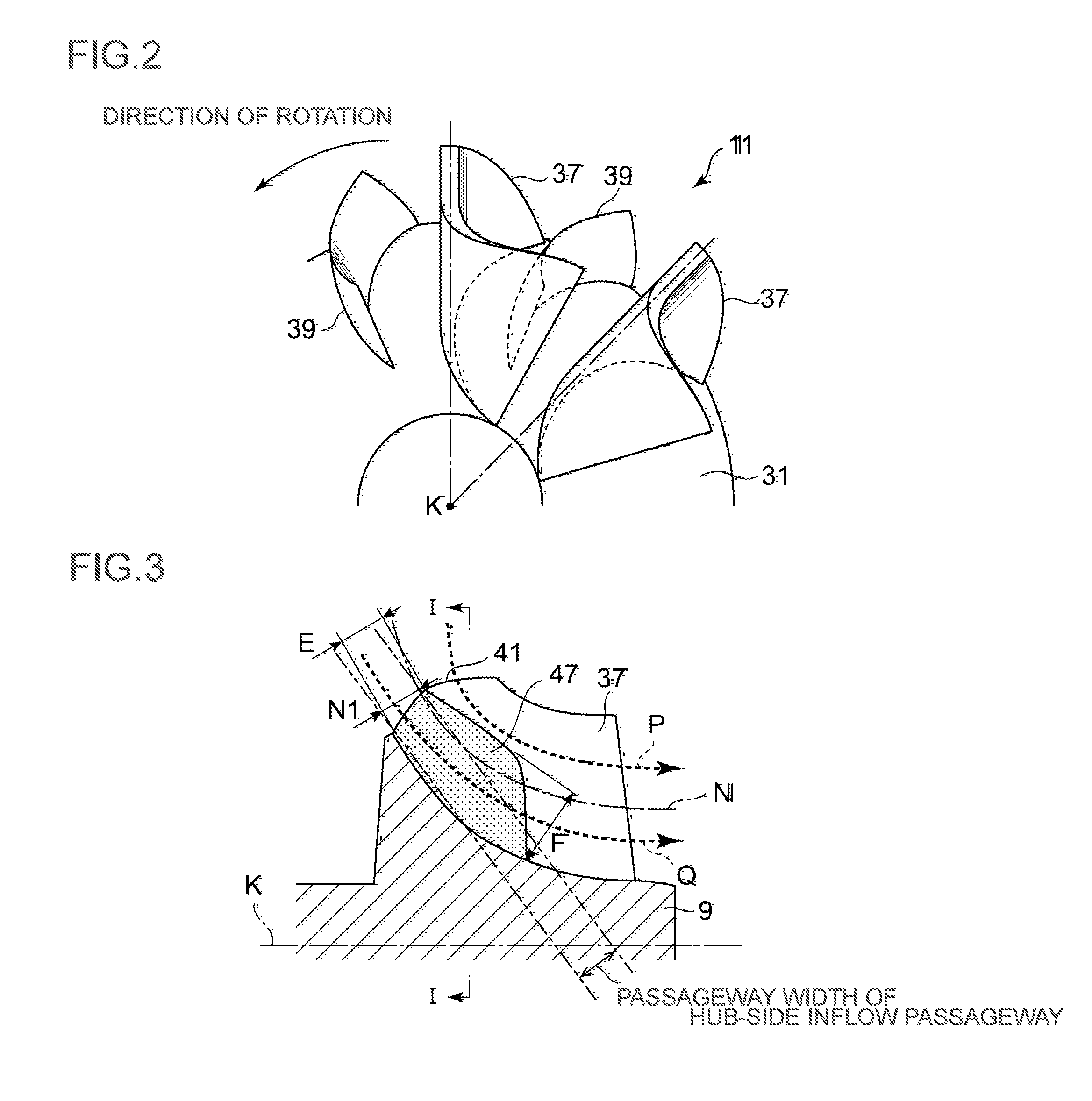
[0118]Next, referring to FIG. 3 to FIG. 5, a second embodiment will be described.

[0119]The second embodiment is a variation of the meridional shape of the intermediate blade 39 of FIG. 1, and an intermediate blade 47 of the second embodiment is such that the height of the rear edge portion is higher than the front edge portion.

[0120]The line N of FIG. 3 denotes a center line on the meridional plane that divides the flow along the main blade 37 into passageway areas of the flow through the shroud-side passageway and the flow through the hub-side passageway based on the ratio between the passageway width of the shroud-side inflow passageway 35 and the passageway width of the hub-side inflow passageway 29.

[0121]The line P denotes the center line of the flow through the shroud-side passageway, and the line Q denotes the center line of the flow through the hub-side passageway.

[0122]Then, the front edge of the intermediate blade 47 coincides with the front edge 41 of the main blade 37, wh...

third embodiment

[0127]Next, referring to FIG. 6, a third embodiment will be described.

[0128]The third embodiment is a variation of the meridional shape of the intermediate blade 39 of FIG. 1, wherein the front edge of an intermediate blade 49 of the third embodiment is provided at a position less than the front edge radius of the main blade 37, and the blade height G1 of the intermediate blade 49 across the entire extent from upstream to downstream is maintained constantly at a substantially equal height to the height N1 of the center line denoted by the line N of FIG. 6 or at a position slightly higher than the center line N.

[0129]As shown in FIG. 6, the front edge of the intermediate blade 49 is set to a radius substantially equal to the radius Rc at which the intermediate blade 49 is attached to the hub 9, and the blade height G1 is set to a height N1+d such that the center line N is included therein.

[0130]As in the first embodiment, the rear edge of the intermediate blade 49 is formed so as to ...


PUM


Abstract

An object is to provide a mixed flow turbine, wherein intermediate blades having an intermediate height are provided between main blades of the mixed flow turbine, thus improving an impulse blade turbine characteristic and reducing the moment of inertia for a rotor blade as a whole, thereby improving the efficiency and transient response. The mixed flow turbine includes: a turbine rotor blade 11; a turbine housing 3; a scroll partition wall 17 dividing a scroll chamber 13; a shroud-side inflow passageway 35 formed on the side of a shroud-side partition wall surface 25; and a hub-side inflow passageway 29 formed on the side of a hub-side partition wall surface 23, wherein the rotor blade 11 includes: main blades 37 formed with a height spanning the entire extent between a hub outer circumferential surface 31 and the inner periphery surface of a shroud portion 15; and intermediate blades 39 arranged in the circumferential direction between the main blades 37 and arranged so as to extend from the inlet portion of the main blades 37 to an intermediate portion and having an intermediate height with respect to the height of the main blades 37, wherein a fluid from the hub-side inflow passageway 29 flows in through front edges of the intermediate blades 39.

Description

TECHNICAL FIELD[0001]The present invention relates to a mixed flow turbine for use in a small gas turbine, a supercharger, an expander, and the like.BACKGROUND ART[0002]With turbochargers required to have transient response, there is a demand for “an improvement in efficiency” for converting the exhaust energy into an increase in the suction pressure, and “an improvement in rotational acceleration” for reducing the “so-called turbo lag”, a delay in the power increase of an engine with a turbocharger.[0003]Therefore, the efficiency of the compressor and the turbine has been improved, and the moment of inertia of the rotor has been reduced by reducing the size and weight of the turbine wheel, thereby improving the response of the turbo engine when accelerating.[0004]Generally, in order to “improve the efficiency aerodynamically”, it is an effective approach, for example, to increase the number of blades to reduce the blade load, but it will increase the weight and increase the inertia...

Claims


Application Information

Patent Timeline
Patent Type & Authority Applications(United States)
IPC IPC(8): F01D5/04F01D1/02
CPCF01D5/048F05D2210/42F01D5/14F01D1/06F05D2240/241F01D17/14F01D1/026F05D2220/40F01D9/00F01D5/141F01D9/026F05D2210/43
Inventor HIGASHIMORI, HIROTAKA
Owner MITSUBISHI HEAVY IND LTD
Why Eureka
Try Eureka