Direct Type Backlight Module Structure

a backlight module and direct type technology, applied in the direction of lighting and heating apparatus, semiconductor devices for light sources, instruments, etc., can solve the problems of large thickness of the backlight module, the difficulty of uniform mixing light at the point light source getting larger, and the slim trend of leds in the prior, so as to reduce the applied amount of leds, reduce production costs, and increase the thickness of the light casing

Active Publication Date: 2015-08-06
SHENZHEN CHINA STAR OPTOELECTRONICS TECH CO LTD
View PDF1 Cites 2 Cited by
  • Summary
  • Abstract
  • Description
  • Claims
  • Application Information

AI Technical Summary

Benefits of technology

[0004]For this reason, the object of the present invention is to provide a direct type backlight module structure to solve the problems that its can not uniformly mix light and the thickness of the light casing is too large. Moreover, the present invention reduces the applied amount of LEDs to decrease the production cost.

Problems solved by technology

However, corresponding light source is converted to point light source of white LEDs from linear light source of conventional CCFLs, so that the difficulty of achieving uniformly mixing light becomes greater.
Therefore, the amount of LEDs applied becomes less, so as to cause the spacing of the arrangement therebetween LEDs larger, further causing the difficulty of the point light source of uniform mixing light getting larger.
Moreover, in the direct type backlight, the high-power white LEDs needs larger thickness of the light casing for avoiding generating the mura of LEDs to completely mix light, so that the thickness of the backlight module is too large to contrary the slim trend of LEDs in the prior art.

Method used


Image

  • Direct Type Backlight Module Structure
  • Direct Type Backlight Module Structure
  • Direct Type Backlight Module Structure

Examples


first embodiment

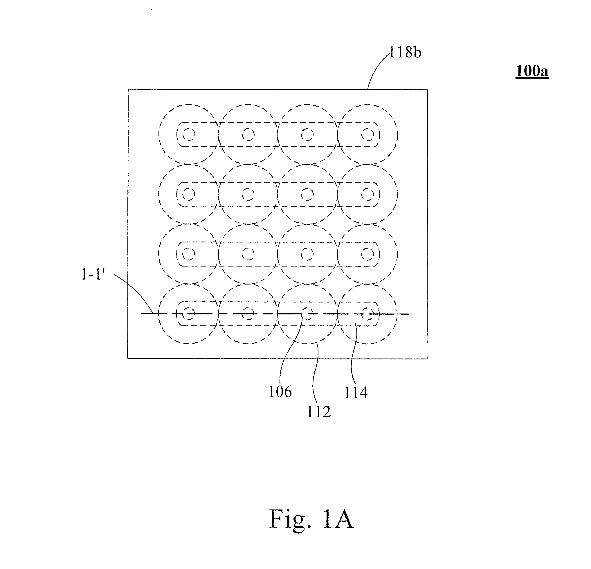
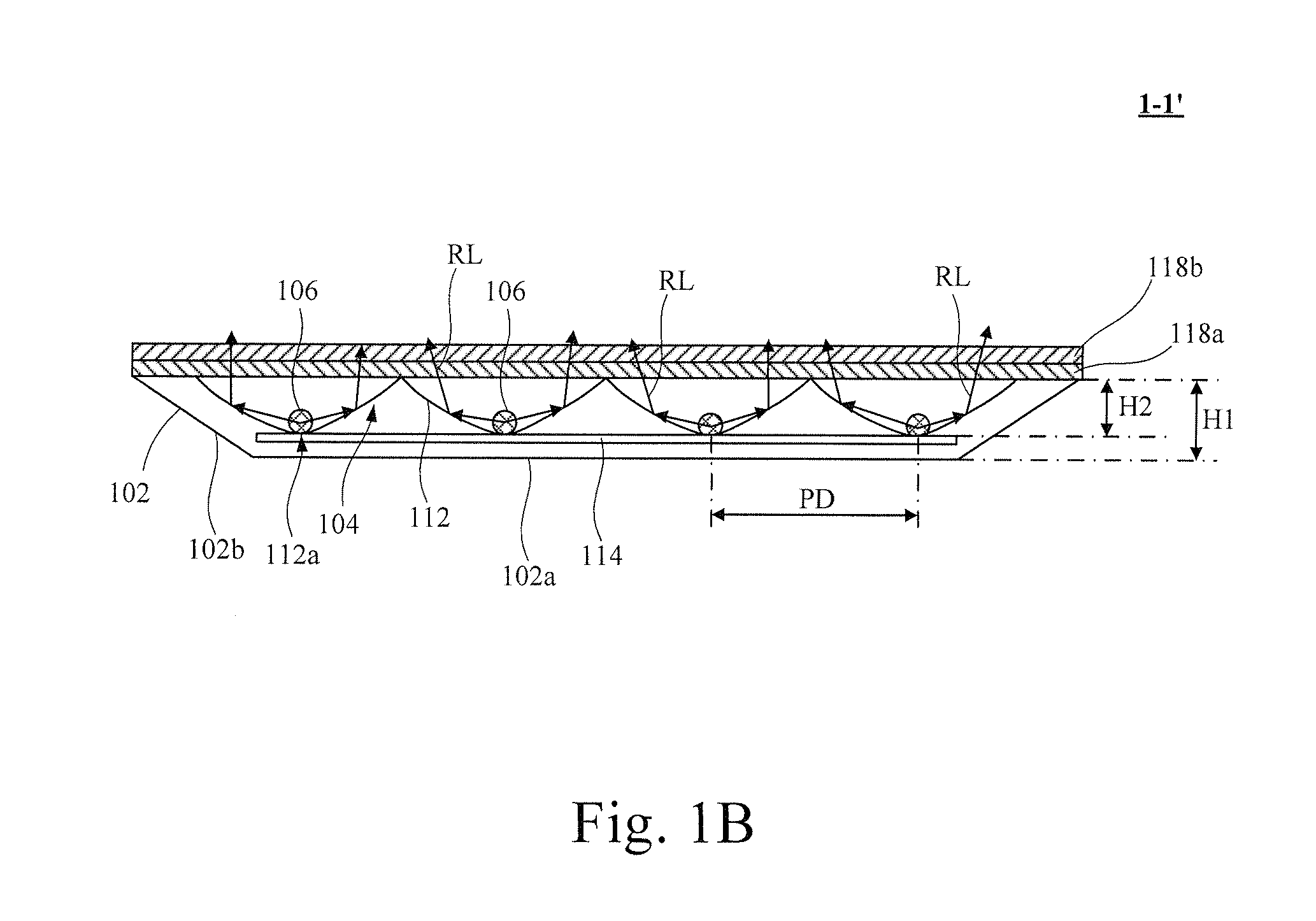
[0022]Referring to FIGS. 1A and 1B, FIG. 1A is a plan view of a backlight module structure 100a according to the present invention; FIG. 1B is a cross-sectional view of being taken along a line 1-1′ according to FIG. 1A of the present invention. As shown in FIGS. 1A and 1B, the direct type backlight module structure 100a comprises a light casing 102, a reflection device 104, a plurality of light sources 106, a diffusion plate 108, a diffusion film 110 and a plurality of strip plate members 114. The light casing 102 has a first height H1. In one embodiment, the light casing 102 comprises a base plate 102a and lateral wall 102b, which are connected to the peripheral edges of the base plate 102a, wherein the lateral wall 102b connects to the base plate 102b for forming the first height H1 of the light casing 102. In another embodiment, the light casing 102 comprises a base plate 102a, and the base plate 102a is bent around the peripheral edges of the light casing 102 for forming the fi...

second embodiment

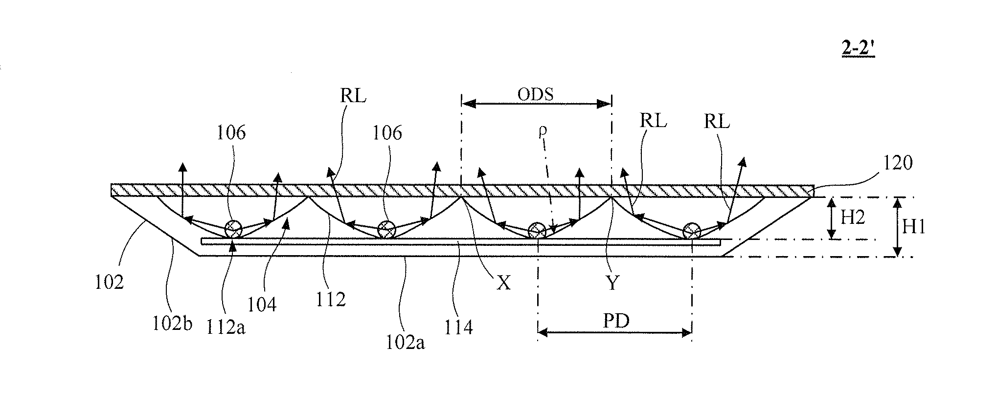
[0026]Referring to FIGS. 2A and 2B, FIG. 2A is a plan view of a backlight module structure 100b according to the present invention; FIG. 2B is a cross-sectional view of being taken along a line 2-2′ according to FIG. 2A of the present invention. As shown in FIGS. 2A and 2B, the direct type backlight module structure 100b comprises a light casing 102, a reflection device 104, a plurality of light sources 106, a brightness enhancement film (BEF) 120 and strip plate members 114. The light casing 102 has a first height H1. In one embodiment, the light casing 102 comprises a base plate 102a and lateral wall 102b connecting to the peripheral edges of the base plate 102a. The lateral wall 102b connecting to the base plate 102b is formed the first height H1 of the light casing 102. The reflection device 104 is disposed on the base plate 102a, and the reflection device 104 comprises a plurality of curved structural units 112, wherein each of the curved structural units 112 is bent to form a ...


PUM


Abstract

The present invention relates to a direct type backlight module structure, which comprises a light casing having a first height, and the light casing comprises a base plate; a reflection device disposed on the base plate, and the reflection device comprises a plurality of curved structural units, and each of the curved structural units is bent to form a second height and an intermediate base, and each of the curved structural units is configured at a predetermined spacing therebetween to be disposed on the base plate; and a plurality of light sources disposed on the reflection device, and each of the light sources is configured at the predetermined spacing therebetween; in which each of the light sources is disposed on the intermediate base of each of the curved structural units of the reflection device.

Description

FIELD OF THE INVENTION[0001]The present invention relates to a backlight module structure, and more particularly to a direct type backlight module structure.BACKGROUND OF THE INVENTION[0002]A backlight module is used to provide the backlight source of liquid crystal displays (LCDs), which is an indispensable and important display component of LCDs. In the prior art, the backlight source of LEDs of a direct type light emitted diode is replaced from conventional cold cathode fluorescent lamps (CCFLs) to white LEDs, and with respect to the conventional CCFLs, the white LEDs is greener and more efficiency. However, corresponding light source is converted to point light source of white LEDs from linear light source of conventional CCFLs, so that the difficulty of achieving uniformly mixing light becomes greater. Furthermore, white LEDs of the direct type light emitted diode generally apply high-power LEDs to reduce the requirement of cost. Therefore, the amount of LEDs applied becomes le...

Claims


Application Information

Patent Timeline
Patent Type & Authority Applications(United States)
IPC IPC(8): F21V7/00F21V9/00
CPCG02F1/133603G02F1/133605F21Y2105/001F21V9/00F21V7/0083F21Y2105/10F21Y2115/10
Inventor WANG, YEWEN
Owner SHENZHEN CHINA STAR OPTOELECTRONICS TECH CO LTD
Why Eureka
Try Eureka