Method and apparatus for determining residual stresses of a component

a residual stress and component technology, applied in the direction of apparatus for force/torque/work measurement, auxillary shaping apparatus, force measurement by measuring optical property variation, etc., can solve the problems of component distortion, affecting the accuracy of residual stress determination, etc., to achieve the effect of accurate determination of residual stress and easy to perform

Inactive Publication Date: 2015-08-06
MTU AERO ENGINES GMBH
View PDF3 Cites 29 Cited by
  • Summary
  • Abstract
  • Description
  • Claims
  • Application Information

AI Technical Summary

Benefits of technology

[0005]It is an object of the present invention to provide a method for determining residual stresses of a component while it is being manufactured by an additive manufacturing process, which method can be used non-destructively on the component,

Problems solved by technology

Such residual stresses may lead to the formation of cracks during build-up of the component, or may result in component distortions during subsequent heat treatment.
However, with these methods, it is only possible to examine s

Method used


Image

  • Method and apparatus for determining residual stresses of a component
  • Method and apparatus for determining residual stresses of a component

Examples


Embodiment Construction

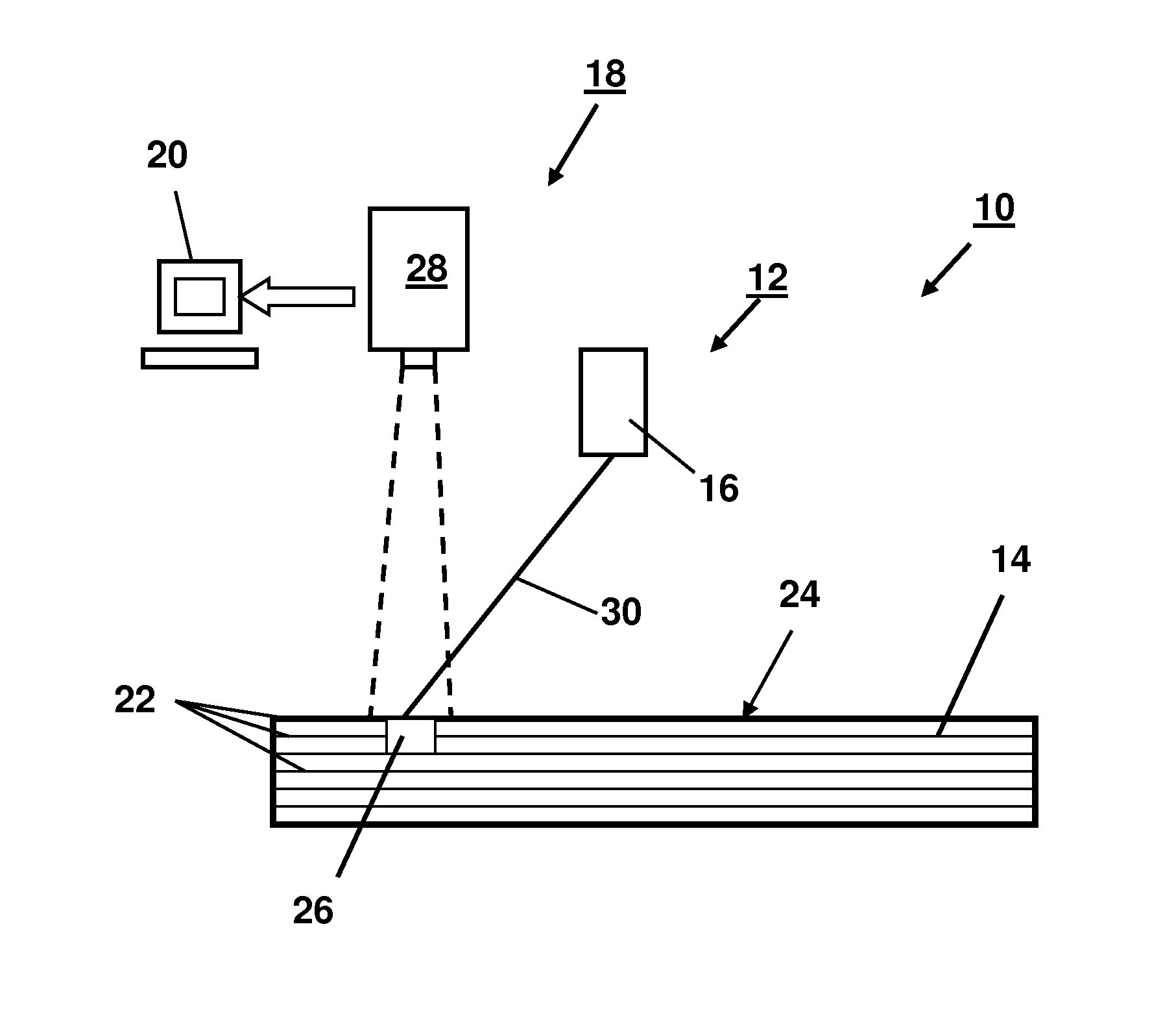
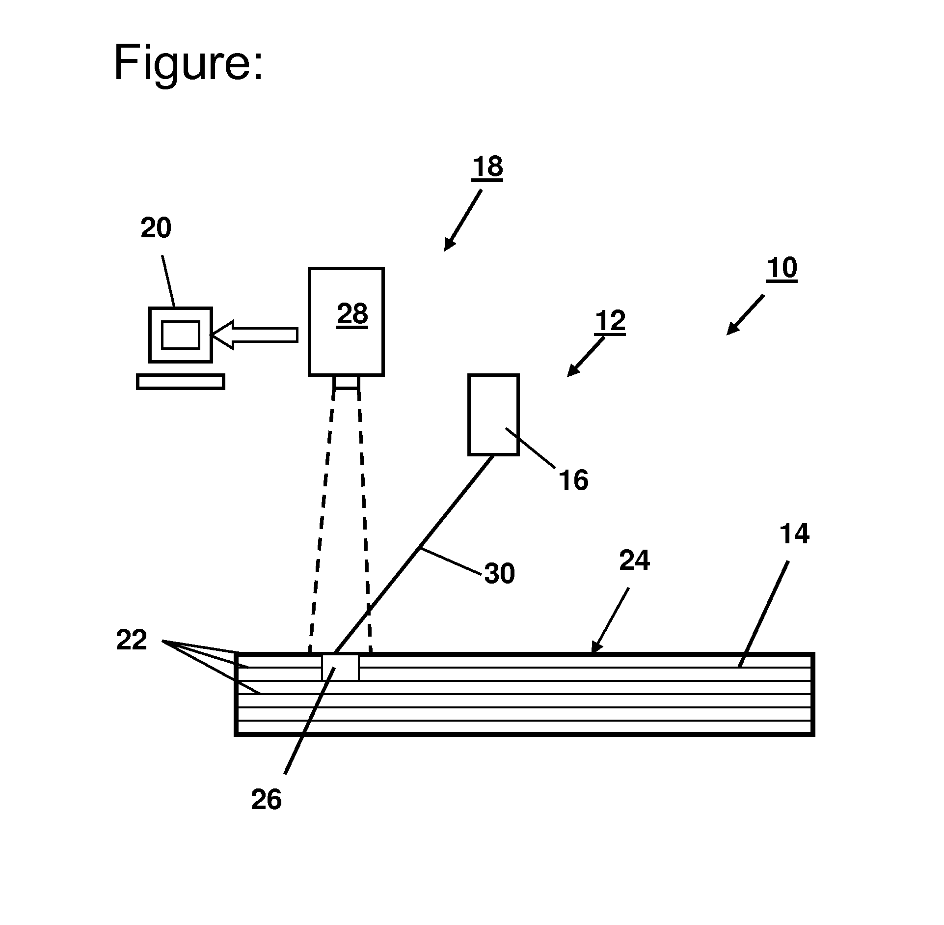
[0021]The FIGURE shows a schematic representation of the apparatus 10 according to the present invention. Apparatus 10 includes an additive manufacturing device 12 for manufacturing a component 14. The additive manufacturing device 12 shown is a device for selective laser melting, which has a laser light source 16.

[0022]In order to manufacture component 14, thin powder layers of a high-temperature resistant metal alloy are deposited in a generally known manner on a platform (not shown) of manufacturing device 12, locally melted by laser 16 or laser beam 30, and solidified by cooling. Subsequently, the platform is lowered, another powder layer is deposited and again solidified.

[0023]This cycle is repeated until component 14 is completed. Component 14 may, for example, be made of up to 2000 component layers 22 and have an overall layer height of 40 to 80 mm The completed component 14 may then be further processed or used immediately. Prior to final completion of component 14, a local ...


PUM

PropertyMeasurementUnit
Depthaaaaaaaaaa
Depthaaaaaaaaaa
Diameteraaaaaaaaaa

Abstract

A method for determining residual stresses of a component (14), in particular a component of an aircraft engine, while it is being manufactured by an additive manufacturing process. The method includes the following steps: creating at least one local melt pool (26) in a surface (24) of the component (14) to be manufactured after a predetermined portion of the component is completed; optically detecting surface distortions and/or elongations occurring at least in a region around the created melt pool (26); and determining the residual stresses of the component (14) which are present at least in the region around the created melt pool (26) based on the optically detected surface distortions and/or elongations. Further an apparatus for determining residual stresses of a component (14) while it is being manufactured by an additive manufacturing process is provided.

Description

[0001]This claims the benefit of German Patent Application DE 10 2014 20 20 20.4, filed Feb. 5, 2014 and hereby incorporated by reference herein.[0002]The present invention relates to a method for determining residual stresses of a component, in particular a component of an aircraft engine, while it is being manufactured by an additive manufacturing process. Moreover, the present invention relates to an apparatus for determining residual stresses of a component while it is being manufactured by an additive manufacturing process.BACKGROUND[0003]During additive manufacture of components using, for example, selective laser melting, typically high residual stresses are produced which are specific to the particular components. Such residual stresses may lead to the formation of cracks during build-up of the component, or may result in component distortions during subsequent heat treatment. Residual stress analyses are typically performed using X-ray methods and / or the so-called hole-dril...

Claims


Application Information

Patent Timeline
IPC IPC(8): G01B11/16B23K26/03G01L1/24B29C67/00B28B1/00B28B17/00B23K26/34B22F3/105
CPCB33Y10/00G01B9/02095B29L2031/3076B29C67/0085B29C67/0077B28B17/00G01L1/24B23K26/345B23K26/032B22F2003/1056B22F3/1055B33Y50/00B28B1/001G01L5/0047G01B11/162B29C64/153B29C64/20B29C64/393Y02P10/25B22F10/28B22F10/38B22F12/90
Inventor BAMBERG, JOACHIMHESSERT, ROLAND
Owner MTU AERO ENGINES GMBH
Why Eureka
Try Eureka