Supercharge Your Innovation With Domain-Expert AI Agents!

Method of manufacturing an inductive module

a manufacturing method and inductive module technology, applied in the manufacture of coils, printed inductances, electrical apparatus, etc., can solve the problems of low production rate, time-consuming, and damage to the structure of the ferromagnetic cor

Inactive Publication Date: 2015-08-06
TAIMAG CORP
View PDF1 Cites 1 Cited by
  • Summary
  • Abstract
  • Description
  • Claims
  • Application Information

AI Technical Summary

Benefits of technology

The present invention provides a method for making an inductive module that solves at least one problem of prior art.

Problems solved by technology

However, such manual operations have shortcomings of being time-consuming and a low production rate.
However, the structure of the ferromagnetic core might be damaged in the hot pressing process, and the ferromagnetic core might become ineffective due to the high temperature of the hot pressing process.
Furthermore, formation of the blind hole should be precisely controlled since the printed circuit board is relatively thin and is likely to be damaged.
Thus, manufacturing costs become high and the yield is unlikely to be improved.

Method used


Image

  • Method of manufacturing an inductive module
  • Method of manufacturing an inductive module
  • Method of manufacturing an inductive module

Examples


Embodiment Construction

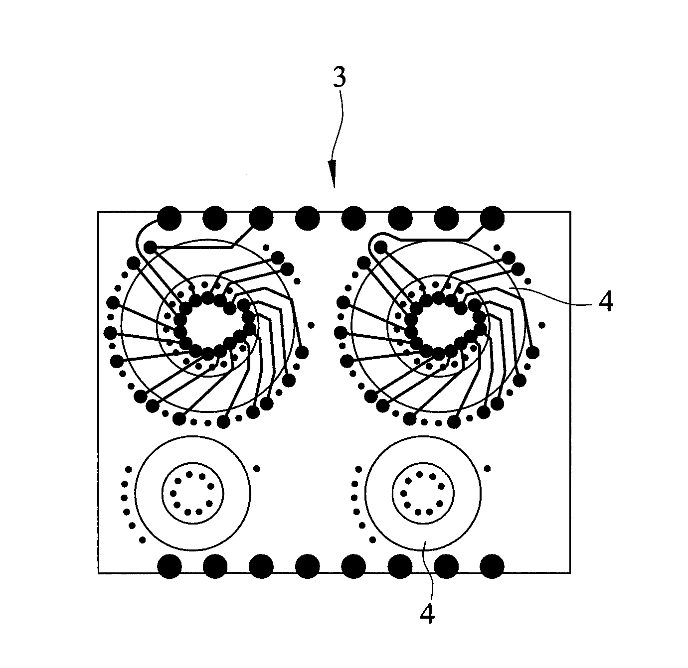
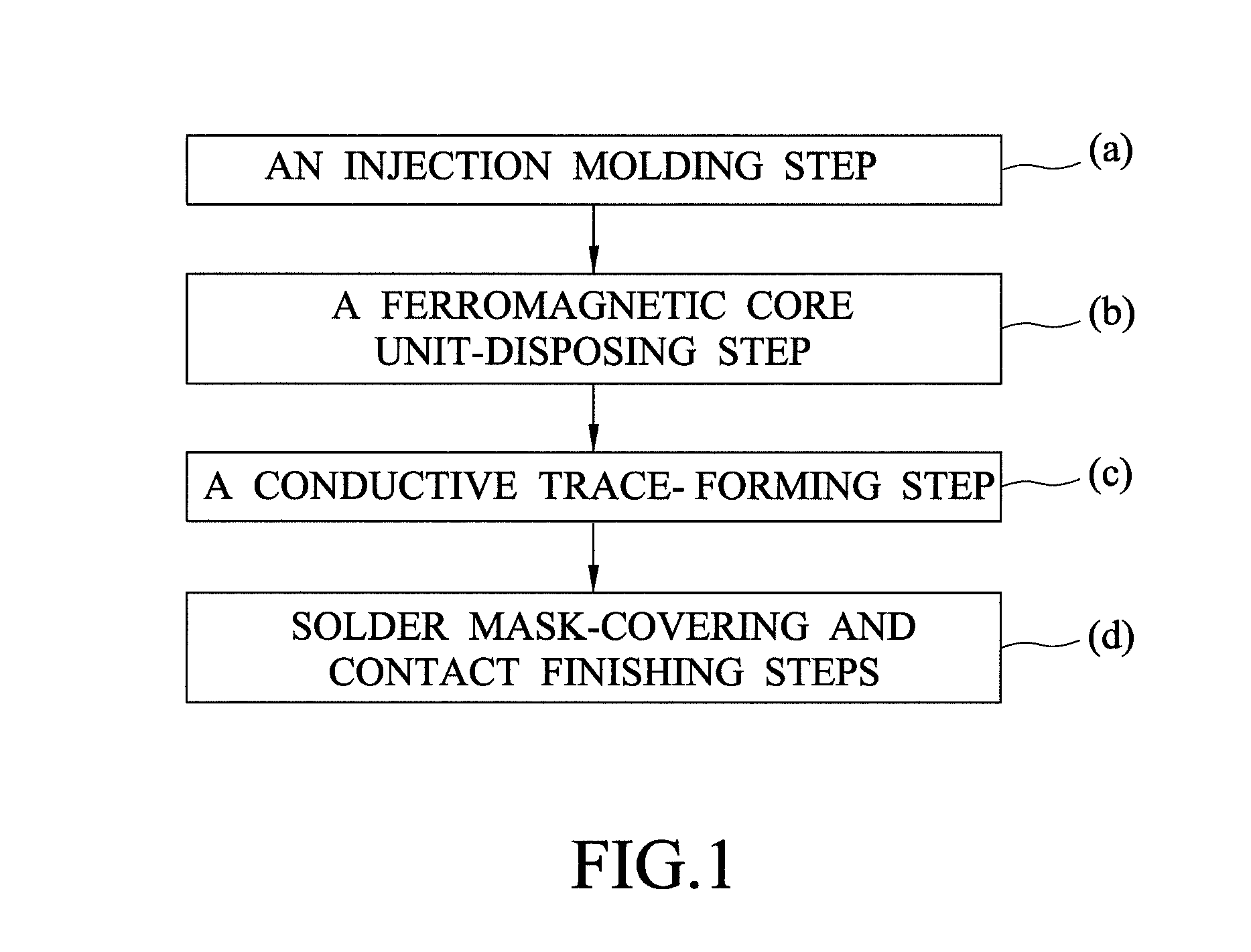
[0028]Referring to FIG. 1, the preferred embodiment of a method of manufacturing an inductive module according to this invention includes: (a) an injection molding step; (b) a ferromagnetic core unit-disposing step; (c) a conductive trace-forming step; and (d) solder mask-covering and contact finishing steps.

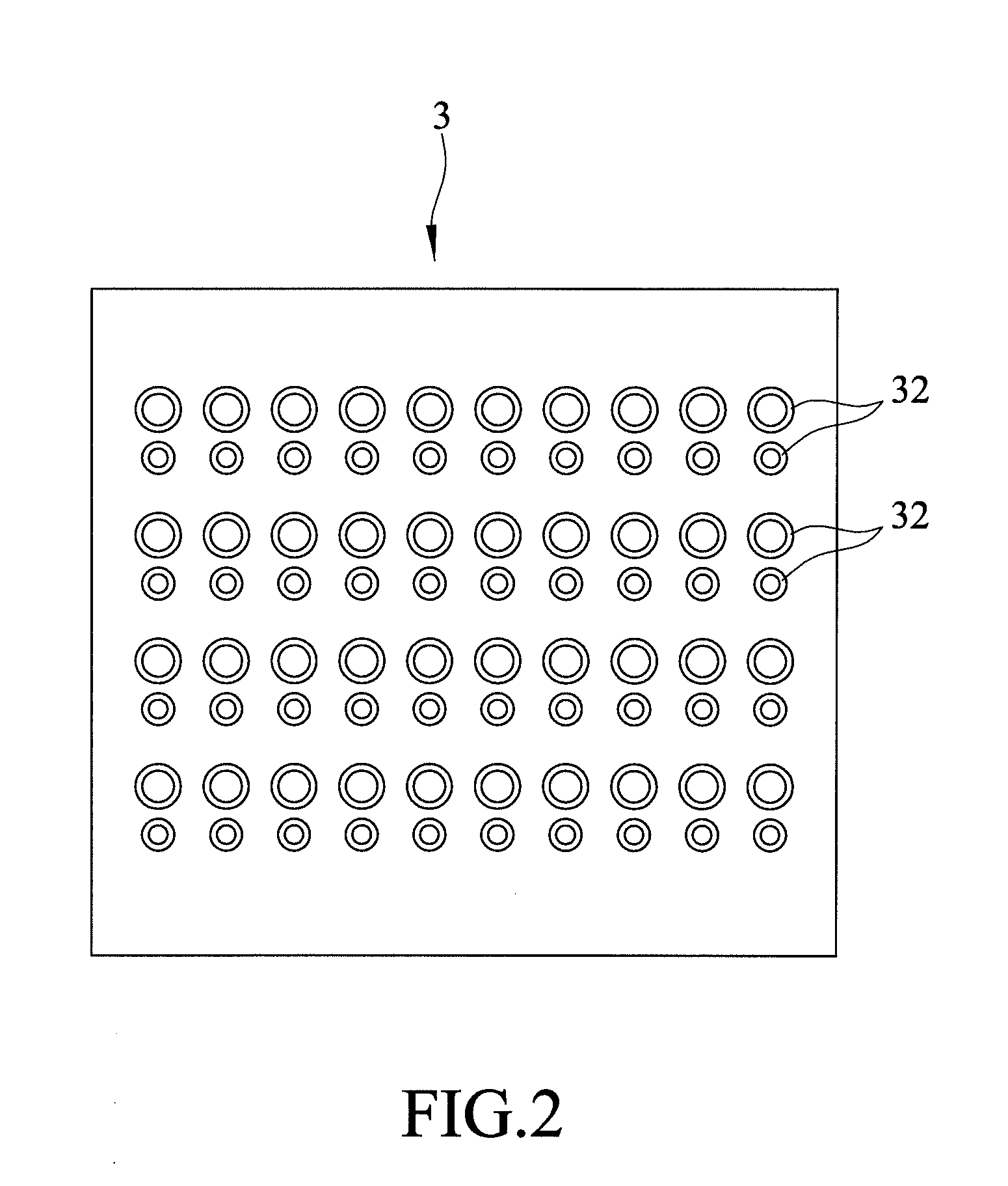
[0029]Referring to FIG. 2, in step (a), a plastic material is subjected to an injection molding process so as to form a substrate 3 that has opposite first and second surfaces and a plurality of receiving spaces 32 indented from the first surface to the second surface. The plurality of receiving spaces 32 are used to receive a plurality of ferromagnetic core units 4 (see FIG. 4), followed by dicing so as to improve processing convenience and reduce manufacturing costs. The plastic material is a thermoplastic material or a thermosetting plastic material. The thermoplastic material is selected from the group consisting of polyphenylene sulfide (PPS), liquid crystal polyester (LCP)...


PUM

PropertyMeasurementUnit
temperatureaaaaaaaaaa
conductiveaaaaaaaaaa
thermosettingaaaaaaaaaa

Abstract

A method of manufacturing an inductive module includes: (a) injection molding a plastic material to form a substrate that has opposite first and second surfaces and at least one receiving space indented from the first surface to the second surface; (b) disposing a ferromagnetic core unit in the receiving space; (c) forming conductive traces on the first and second surfaces of the substrate and forming conductive vias through the substrate, each of the conductive traces being electrically connected to a corresponding pair of the conductive vias; and (d) covering the conductive traces with a solder mask such that a part of the conductive traces are exposed to serve as contacts, followed by subjecting to a contact finishing process.

Description

BACKGROUND OF THE INVENTION[0001]1. Field of the Invention[0002]This invention relates to a method of manufacturing an inductive module.[0003]2. Description of the Related Art[0004]A conventional inductive device, such as an inductor, a transformer, etc., is composed of one or more windings wound around a ferromagnetic core that is made from a ferromagnetic material. Electromagnetic effects occur between the winding and the ferromagnetic core when electric current flows through the winding. For producing smaller transformers, processes of winding the windings, usually in the form of enamel-covered wires, around the ferromagnetic core still rely on manual labor. However, such manual operations have shortcomings of being time-consuming and a low production rate.[0005]In order to solve the above shortcomings, the ferromagnetic core is embedded in a printed circuit board (PCB), and vias are formed in the PCB by drilling and electroplating as a winding.[0006]Generally, a printed circuit ...

Claims


Application Information

Patent Timeline
Patent Type & Authority Applications(United States)
IPC IPC(8): H01F41/04
CPCH01F41/046H01F2017/002
Inventor CHEN, PIN-HUNG
Owner TAIMAG CORP
Features
  • R&D
  • Intellectual Property
  • Life Sciences
  • Materials
  • Tech Scout
  • Unparalleled Data Quality
  • Higher Quality Content
  • 60% Fewer Hallucinations
Learn More