Aortic graft device

a graft device and aortic valve technology, applied in the field of aortic valve devices, can solve the problems of increasing the risk of complications associated with an operation, poor health, and sudden death of aortic valve damage, and achieves the effects of reducing bending force, facilitating handling and placement of the valve device, and minimizing time spen

Active Publication Date: 2015-08-13
COOK MEDICAL TECH LLC
View PDF0 Cites 5 Cited by
  • Summary
  • Abstract
  • Description
  • Claims
  • Application Information

AI Technical Summary

Benefits of technology

The patent describes a device used in surgery to repair damaged blood vessels in the body, particularly in the aorta. The device has a ring-shaped fixing mechanism that allows sutures to be passed through easily, making the surgical procedure faster and more secure. The fixing ring is made from a stiffer material than the graft or corrugated portion of the device, which ensures a stable structure into which sutures can be passed. The graft portion can also have side branches to accommodate branch arteries, and the distal end area can be smoothly connected to the aortic wall or other graft. The device can be pre-curved to make it easier to position and suture in place, and it is designed to be flexible and minimize trauma to the patient.

Problems solved by technology

If a significantly large aneurysm is not treated, it can rupture with abrupt fatal blood loss, either into the abdominal or thoracic cavity of the patient.
Patients diagnosed with aortic aneurysms are often in poor health due to other illnesses which increase the risk of complications associated with an operation.
However, adjacent the heart the flow rate of blood through the aorta is so high that the risk of dislocation of the proximal stent is considerable.
Dissections of the type in which the ascending aorta is involved pose a particular problem.
The surgeon thus has an extremely short time to prepare and perform surgery.
A problem with this procedure is that a surgeon has difficulties in suturing as a result of the fact that the rounded edge is thin, limp and lacks springiness.
As a result of this, the suturing operation can take longer than necessary, which is undesirable and potentially dangerous.

Method used


Image

  • Aortic graft device
  • Aortic graft device
  • Aortic graft device

Examples


Embodiment Construction

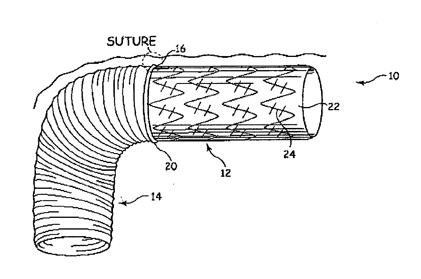
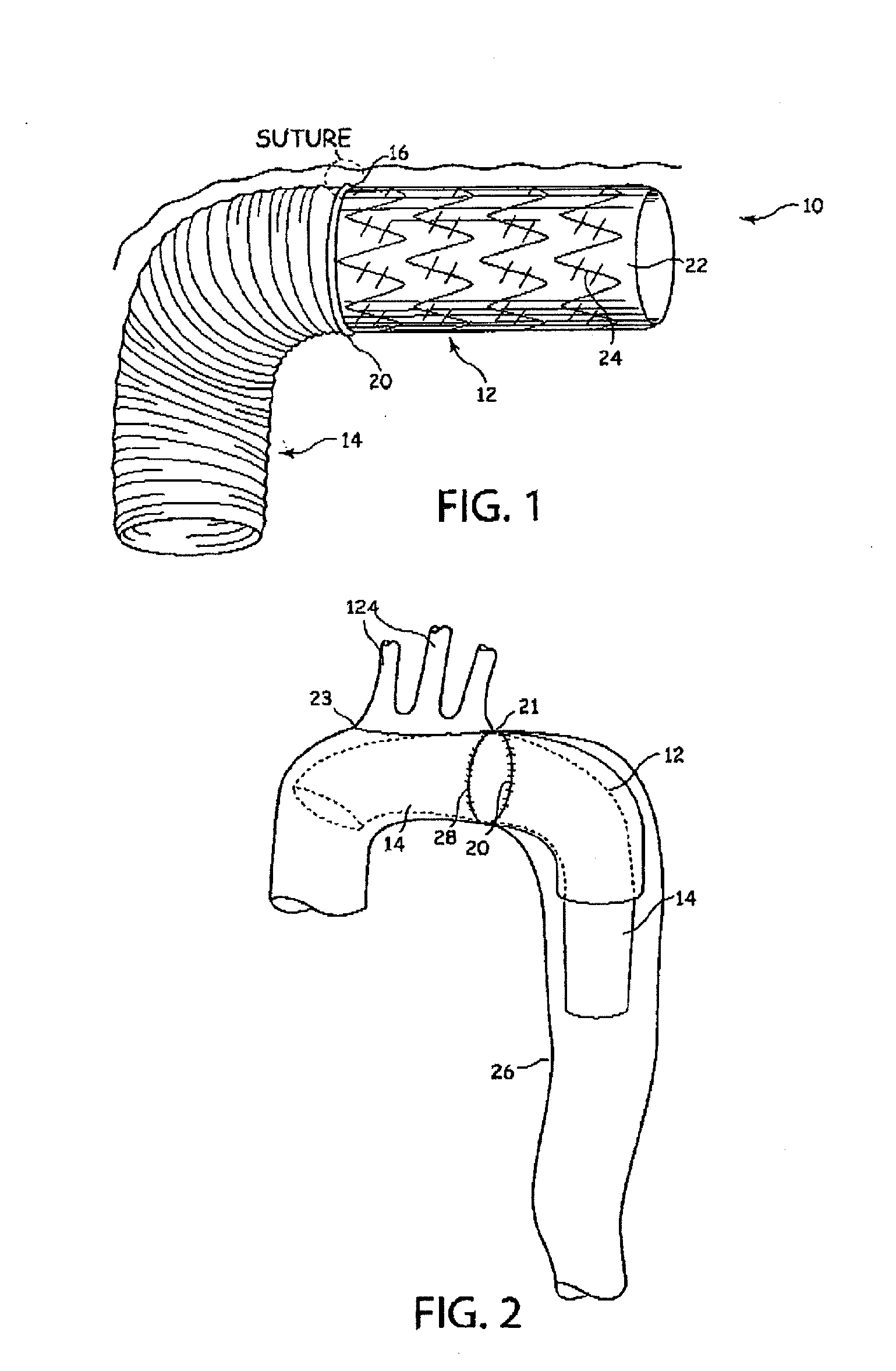
[0034]Referring to FIG. 1, the aortic graft implant 10 shown includes an aortic graft section 12 and a corrugated or elephant trunk section 14. The aortic graft section 12 is tubular and has a proximal end 16 with a proximal opening 18 (not visible in FIG. 1). In the present context proximal is used to denote locations closer to the heart or in an upstream direction relative to aortic blood flow, whereas distal denotes locations more distant from the heart.

[0035]The graft section 12 and any possible graft extensions thereto which are provided can be made of a pliable material, such as expanded polytetrafluoroethylene (PTFE), woven polyester or another biocompatible material, for long term stability in the vascular system. Graft materials are well known in the art and the material can also include biodegradable strands as part of the material.

[0036]The graft section 12 is at least partially non-corrugated. It can have corrugations along part of its length and / or circumference but it ...


PUM


Abstract

An aortic graft device (10) is provided with a graft portion (12) integrally fixed to a corrugated trunk portion (14). A fixing ring (16) is provided between the graft and trunk portions. The trunk portion (14) can be everted into the graft portion, leaving the fixing ring (16) at an extremity of the device for suturing purposes. The fixing ring (16) is preferably made from a relatively stiff material such as a compressed foam or rubber like material, which provides a relatively solid component for a surgeon to hold during suturing and which can provide a strong support for sutures.

Description

RELATED APPLICATIONS[0001]The present patent document is a continuation of application Ser. No. 11 / 998,532, filed Nov. 30, 2007, which claims the benefit of the filing date under 35 U.S.C. §119(e) of Provisional U.S. Patent Application Ser. No. 60,861,853, filed Nov. 30, 2006. All of the foregoing applications are hereby incorporated by reference.TECHNICAL FIELD[0002]The present invention relates to an aortic graft device provided with a graft portion and a corrugated portion extending from the graft portion.BACKGROUND OF THE INVENTION[0003]An aortic graft is an endovascular prosthesis for placement in the aorta, in a weakened area, such as an aneurysm or an aortic dissection. An aortic aneurysm is an abnormal dilation or enlargement of the arterial wall of the aorta. If a significantly large aneurysm is not treated, it can rupture with abrupt fatal blood loss, either into the abdominal or thoracic cavity of the patient.[0004]An aortic graft is typically made of a tube of pliable ma...

Claims


Application Information

Patent Timeline
Patent Type & Authority Applications(United States)
IPC IPC(8): A61F2/07A61F2/89A61F2/06
CPCA61F2/07A61F2/89A61F2220/0008A61F2210/0014A61F2002/075A61F2/06A61F2002/061A61F2/82A61F2002/065A61F2220/0075
Inventor RASMUSSEN, ERIK E.CHRISTIANSEN, FRANK K.
Owner COOK MEDICAL TECH LLC
Why Eureka
Try Eureka