Methods and Apparatus for Laser Cleaning

a laser cleaning and apparatus technology, applied in the field of methods, can solve the problems of high water and power consumption of machines, requiring subsequent drying, and process leaving the articles quite wet,

Active Publication Date: 2015-08-13
WOODROW SCI LTD
View PDF10 Cites 25 Cited by
  • Summary
  • Abstract
  • Description
  • Claims
  • Application Information

AI Technical Summary

Benefits of technology

[0007]In consideration of one or more of the disadvantages with conventional cleaning methods and apparatus, the present inventor has devised novel processes and apparatus for cleaning substrates, such as su

Problems solved by technology

Such machines have a high consumption of both water and power, with an average domestic washing machine using between 9-10 litres of water and consuming approximately 0.75 KW-hour electricity per wash load.
Once the items are cleaned, the very nature of the cleaning process leaves the articles quite wet and requires subsequent drying, either in an inefficient machine such as a commercial tumble drier or through inefficient use of a building's heating system (radiators, etc.) or through outside drying via direct sunlight and/or wind.
Dry cleaning processes typ

Method used


Image

  • Methods and Apparatus for Laser Cleaning
  • Methods and Apparatus for Laser Cleaning
  • Methods and Apparatus for Laser Cleaning

Examples


working examples

[0146]FIG. 20 shows an example of a cotton fabric 300 having been contaminated with a dark oil from an engineering workshop. The piece of fabric is contaminated with a dark machine shop oil 302 and has been exposed to a pulsed laser source in a square region of approximately 15×15 mm dimension 304. The laser parameters include wavelength 1064 nm, pulse duration 20 nanoseconds and pulse energy of 800 uJ at a pulse repetition rate of 25 KHz. The output from the laser is focussed to spot diameter of approximately 30 um and scanned across the sample in a square pattern. The sample was soaked in water prior to cleaning which enhanced the process of contaminant removal.

[0147]FIG. 21a shows another example of a cleaned fabric sample 310 comprising a blue and white cotton shirt. The shirt, prior to cleaning with an apparatus and process according to the present invention, 312 had been contaminated with an orange coloured food stain 314. FIG. 21a shows the stained shirt after several attempt...


PUM

PropertyMeasurementUnit
Temperatureaaaaaaaaaa
Fractionaaaaaaaaaa
Percent by massaaaaaaaaaa

Abstract

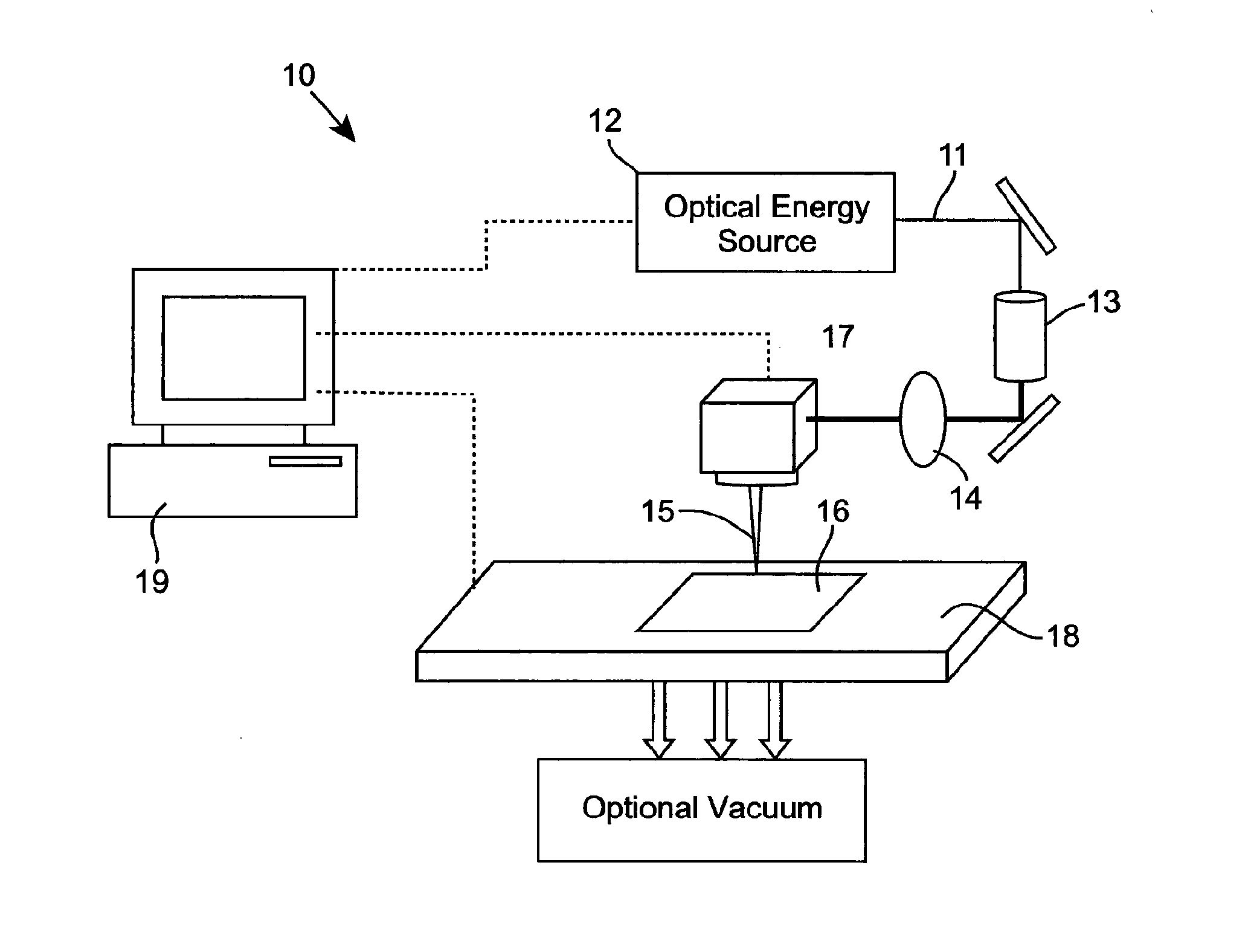
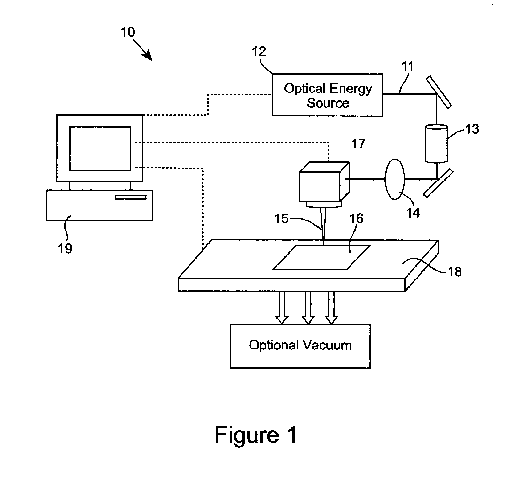
A method of cleaning a substrate (16, 24, 34, 64, 71, 82, 102, 165, 171, 181, 201, 300, 310) with optical energy can comprise applying optical energy from a source of optical energy (12, 21, 31, 91, 103, 114, 121, 131, 141, 151, 164, 191, 202) to the substrate. The method can comprise applying the optical energy to a substrate having a cleaning agent applied thereto, the optical energy having one or more optical parameters selected for cleaning the substrate. The method can comprise reading data from a data bearing element (173) associated with the substrate, communicating the data to a processor (154) associated with a cleaning appliance (10, 30, 40, 60, 70, 80, 90, 110, 120, 130, 140, 150, 161, 200) comprising the source of optical energy, wherein the processor, responsive to the communicated data, controls the cleaning of the substrate with the optical energy. The method can comprise slidingly contacting the substrate with a work surface, said work surface comprising an aperture (83, 117) and emanating optical energy from the aperture for cleaning the substrate. A cleaning appliance can comprise an appliance body (80, 90, 104, 125) comprising an aperture for emanating optical energy for cleaning the substrate and an optical transmission pathway arranged for propagating optical energy received from an optical energy source to said aperture. The appliance can be adapted and constructed for delivering a cleaning agent to the substrate. The appliance can include a processor, a data interface in communication with the processor, and can be configured such that the processor outputs signals that control the cleaning of the substrate, the processor being configured for controlling, responsive to data received by the data interface and via the output signals, the substrate cleaning. The cleaning appliance can include a suction pump (142) for removing material from the substrate.

Description

FIELD OF THE INVENTION[0001]The present invention relates to an apparatus and methods of cleaning substrates using optical energy. More particularly, the invention is concerned with using optical energy to clean substrates, including the combined use of optical energy and cleaning agents to enhance cleaning, such as, for example, enhancing stain removal.BACKGROUND[0002]Conventional cleaning apparatus and processes typically utilise an aqueous method or a method which utilises chemicals. Consider, for example, household washing machines or dry cleaning, which is more commonly used within industrial cleaning processes.[0003]Domestic cleaning of clothes or other fabric articles typically involves hand washing processes or more commonly front or top-loaded drum-style washing machines which employ both an aqueous and mechanical cleaning process, often requiring large amounts of detergents and stain removal chemicals. Such machines have a high consumption of both water and power, with an ...

Claims


Application Information

Patent Timeline
IPC IPC(8): D06M10/00D06L3/00D06F75/14B08B7/00
CPCD06M10/005D06F75/14D06L3/00B08B7/0042B08B7/0035C11D3/3947C11D11/007D06F35/00D06F43/002D06F75/246D06L1/00D06L4/50
Inventor CLOWES, JOHN REDVERS
Owner WOODROW SCI LTD
Why Eureka
Try Eureka