Hydraulic work machine

a hydraulic work machine and hydraulic technology, applied in the direction of machines/engines, hybrid vehicles, instruments, etc., can solve the problems of affecting the use of complex and expensive materials, and the degradation of fuel efficiency of the engine system, so as to prevent the operating point from moving too fast, improve the combustion state of the engine, and improve the effect of fuel efficiency

Active Publication Date: 2015-08-13
NIHON KENKI CO LTD
View PDF0 Cites 16 Cited by
  • Summary
  • Abstract
  • Description
  • Claims
  • Application Information

AI Technical Summary

Benefits of technology

[0030]In the present invention, when the operating point of the engine is to be moved by changing the rotational speed and torque of the engine, since the target rotational speed and target torque of the engine can be set so as to change the rotational speed and torque of the engine along the predetermined route, this characteristic prevents the operating point of the engine from passing through a fuel-efficiently unfavorable region or a region of a high air-pollutant content in gas emissions while moving, and thus improves the combustion state of the engine under the transient state with the changing engine speed and torque.
[0031]Additionally in the present invention, when the operating point of the engine is to be moved by changing the rotational speed and torque of the engine, since not only the target rotational speed and target torque of the engine are set so as to change the rotational speed and torque of the engine along the predetermined route, but also the respective rates of change of the target engine speed and torque are limited, these characteristics prevent the operating point from moving too fast and degrading fuel efficiency, and emissions of air pollutants from increasing, and leads to improved engine internal combustion under the transient state that the engine changes in speed and torque.

Problems solved by technology

Market needs for improved fuel economy are also becoming stronger with the rising fuel costs and the continuing business recession.
The gas emissions aftertreatment devices such as DPFs and urea SCR systems, however, usually use complex and expensive materials.
Accordingly, engine systems having a gas emissions aftertreatment device(s) are considerably expensive, compared with engine systems not having one.

Method used


Image

  • Hydraulic work machine
  • Hydraulic work machine
  • Hydraulic work machine

Examples


first embodiment

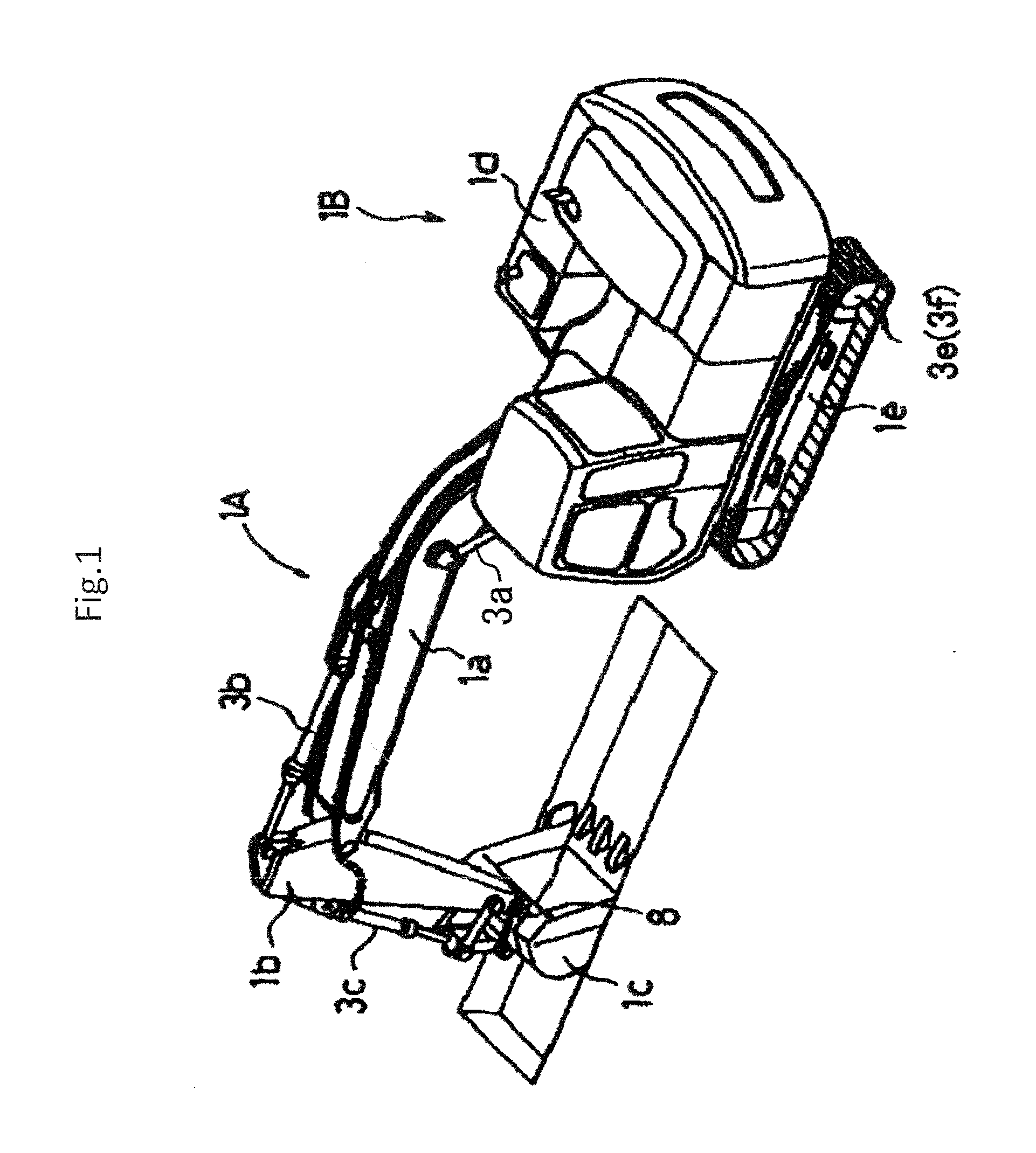
[0046]FIG. 1 is an external view of a hydraulic excavator, an example of a hydraulic work machine according to a first embodiment of the present invention.

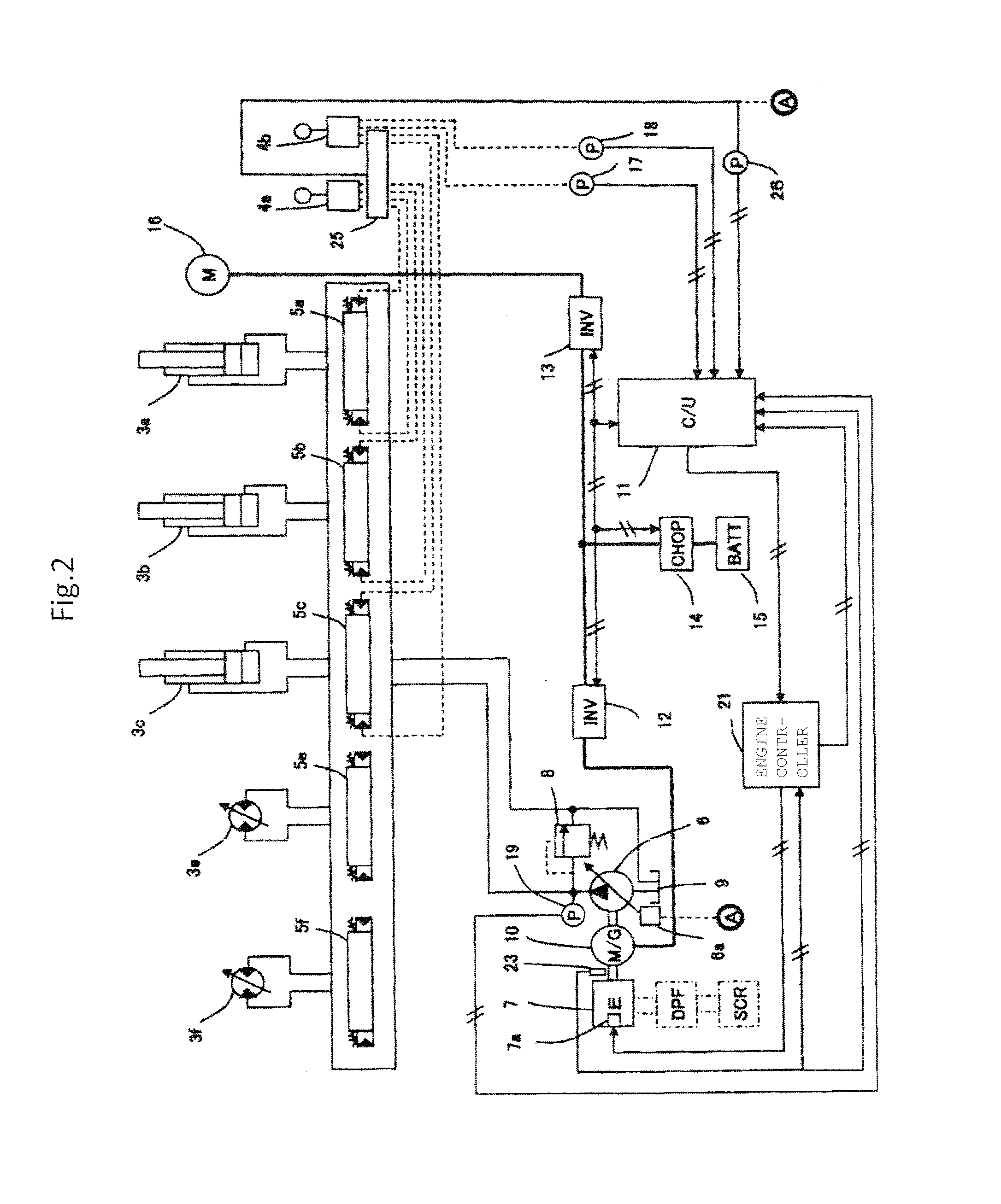
[0047]The hydraulic excavator includes an articulated type of front implement 1A having a boom 1a, an arm 1b, and a bucket 1c, each constructed to pivot in a vertical direction, and a vehicle body 1B having an upper swing structure 1d and a lower traveling structure 1e. The boom 1a of the front implement 1A has a proximal end supported at a front portion of the upper swing structure 1d so as to be pivotable in the vertical direction. The boom 1a, the arm 1b, the bucket 1c, the upper swing structure 1d, and the lower travel structure 1e are driven by a boom cylinder 3a, an arm cylinder 3b, a bucket cylinder 3c, a swing motor 16 shown in FIG. 2, and left and right traveling motors 3e and 3f, respectively. Operation of the boom 1a, arm 1b, bucket 1c, and upper swing structure 1d, is specified by hydraulic actuating signals (control p...

second embodiment

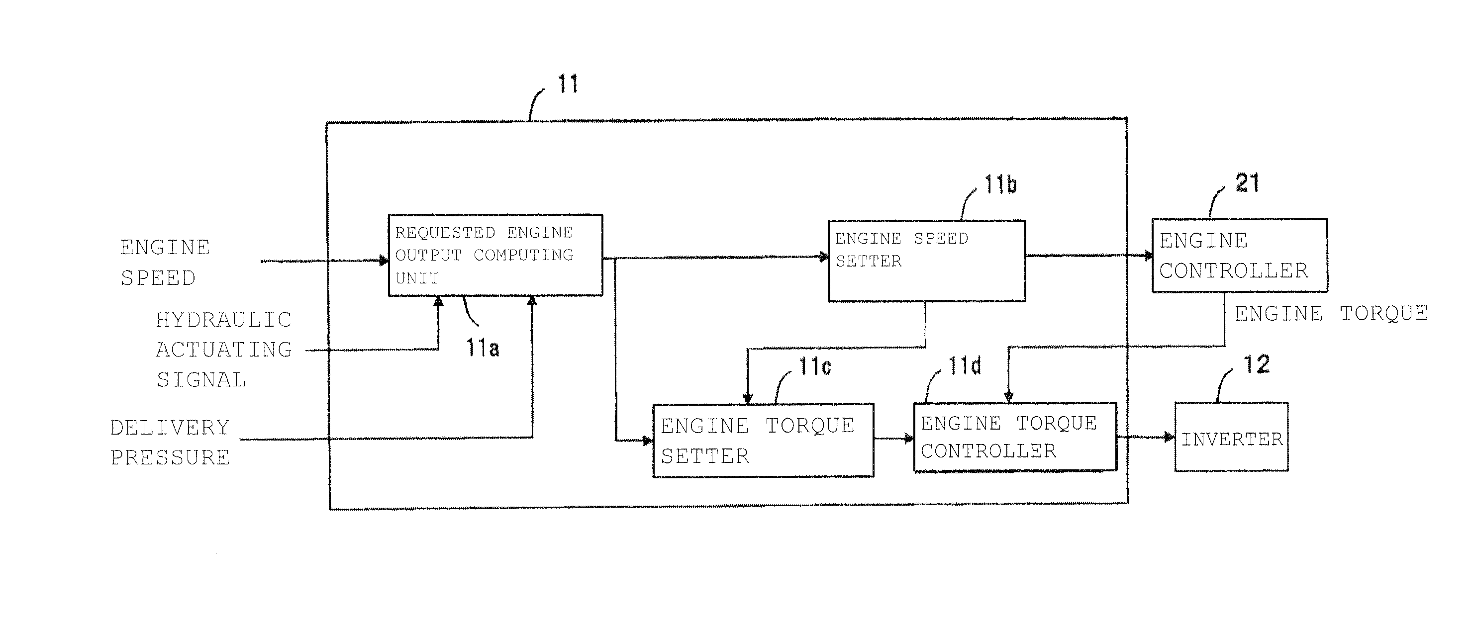
[0096]FIG. 9 is a functional block diagram that shows details of engine speed and torque control processing by a vehicle body controller 11 (see FIG. 2) of an actuator driving system in a second embodiment of the present invention. The vehicle body controller 11 includes a requested engine output computing unit 11a, an engine speed setter 11Ab, an engine torque setter 11Ac, and an engine torque controller 11d. The requested engine output computing unit 11a and the engine torque controller 11d are the same as those described in the first embodiment with reference to FIG. 3. The engine speed setter 11Ab computes a target rotational speed of an engine 7 from a rotational speed of the engine 7 and the engine 7 output requested. The engine torque setter 11Ac computes a target torque of the engine 7 from the requested engine 7 output and the engine 7 speed.

[0097]In the present embodiment, the requested engine output computing unit 11a, the engine speed setter 11Ab, and the engine torque s...


PUM


Abstract

This invention is a hydraulic work machine having an electric assist motor coupled to an engine and a hydraulic pump, in the hydraulic work machine of which, a rotational speed and torque of the engine are controlled so that an operating point of the engine moves along a predetermined route for yielding a combustion state of the engine under a transient state that the engine changes in speed and torque. A target speed and torque of the engine 7 are set so that the rotational speed and torque of the engine 7 will change along a predetermined route F in a running region of the engine, respective rates of change of the target rotational speed and torque of the engine 7 are limited, and the engine 7 is controlled to yield the target engine speed. In addition, torque of the assist motor 10 is controlled to yield the target torque of the engine.

Description

TECHNICAL FIELD[0001]The present invention relates generally to hydraulic excavators and other hydraulic work machines, and more particularly, to a hybrid-driven hydraulic work machine having an electric assist motor driven by an electricity storage device as well as an engine.BACKGROUND ART[0002]In recent years, regulations relating to gas emissions from the engines of hydraulic work machines such as hydraulic excavators have been more tightened with each passing year. Market needs for improved fuel economy are also becoming stronger with the rising fuel costs and the continuing business recession.[0003]In response to the gas emissions regulations, engine manufacturers and others have made efforts toward the reduction of the particulate matter (PM) and nitrogen oxides (NOx) contained in gas emissions, in particular, and techniques for sophisticating combustion control have been developed in large numbers to date. At the same time, technology has also been developed that is intended...

Claims


Application Information

Patent Timeline
Patent Type & Authority Applications(United States)
IPC IPC(8): E02F9/20F02D29/04B60W10/30E02F9/22B60W10/06B60W10/08
CPCE02F9/2075B60W10/06B60W10/08B60W2300/17E02F9/2246F02D29/04B60W10/30B60K6/485B60W20/00E02F9/2296F02D29/02Y02T10/62E02F9/20F02D29/00Y02T10/64
Inventor HOSHINO, MASATOSHIISHIHARA, SHINJIFUJISHIMA, KAZUO
Owner NIHON KENKI CO LTD
Why Eureka
Try Eureka