Ventilation unit

Inactive Publication Date: 2015-08-13
SPAL AUTOMOTIVE
View PDF7 Cites 6 Cited by
  • Summary
  • Abstract
  • Description
  • Claims
  • Application Information

AI Technical Summary

Benefits of technology

[0012]Another aim is to propose a ventilation unit whi

Problems solved by technology

Consider for example that the engine compartment may contain a water radiator, small radiators for the engine oil, for the air conditioning system, for the transmission, for cooling the catalytic converter, and

Method used


Image

  • Ventilation unit
  • Ventilation unit
  • Ventilation unit

Examples


Example

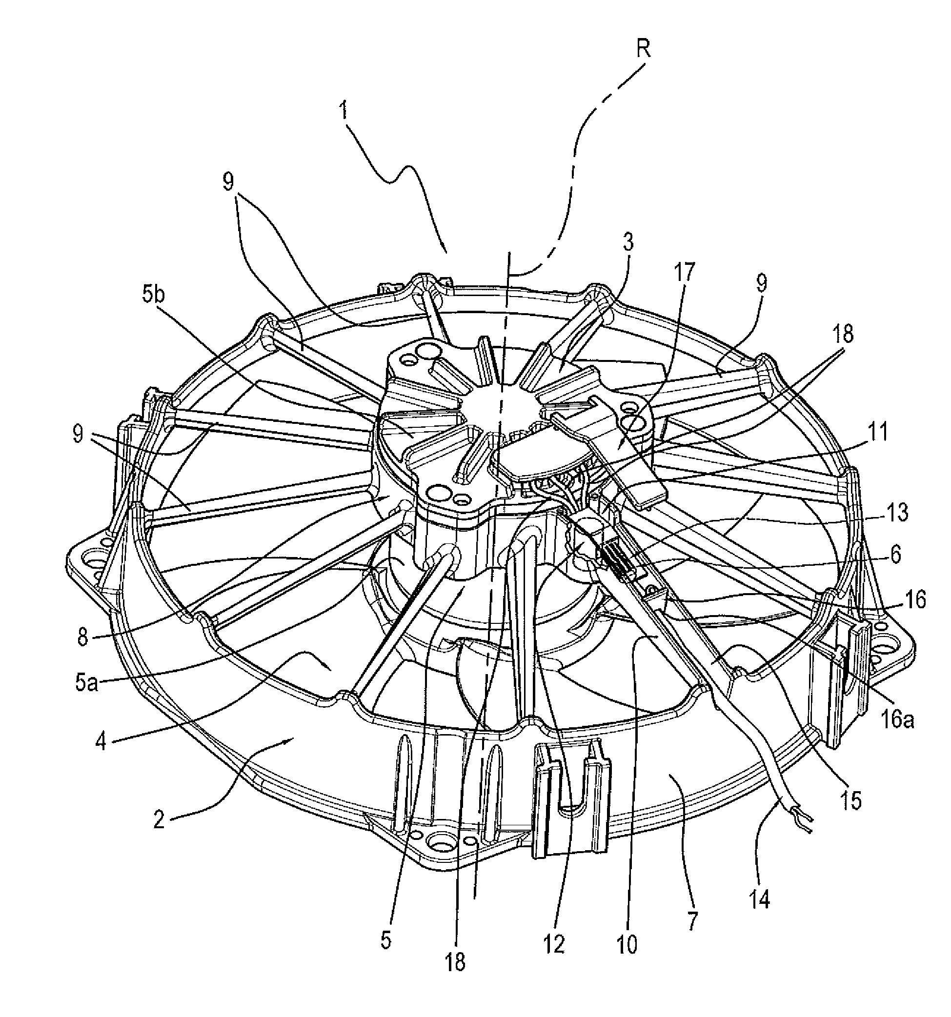
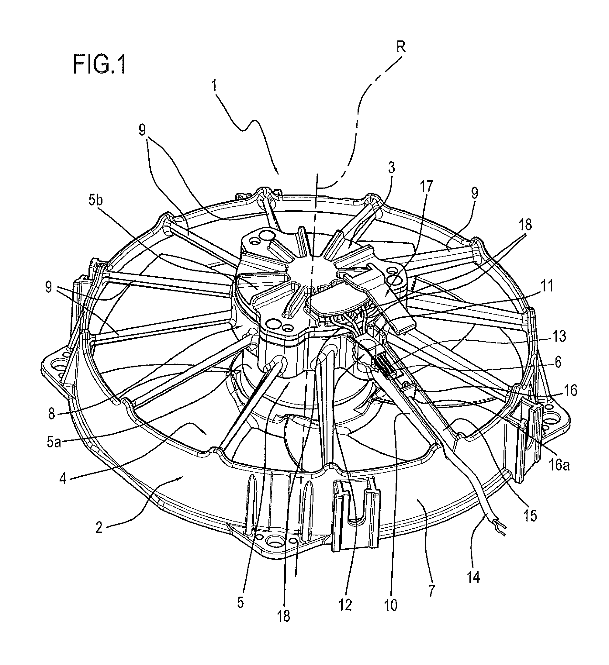
[0018]With reference to the accompanying drawings, in particular FIG. 1, the numeral 1 denotes a ventilation unit according to this invention.

[0019]The ventilation unit 1 comprises an electric fan and a shroud 2 supporting the electric fan.

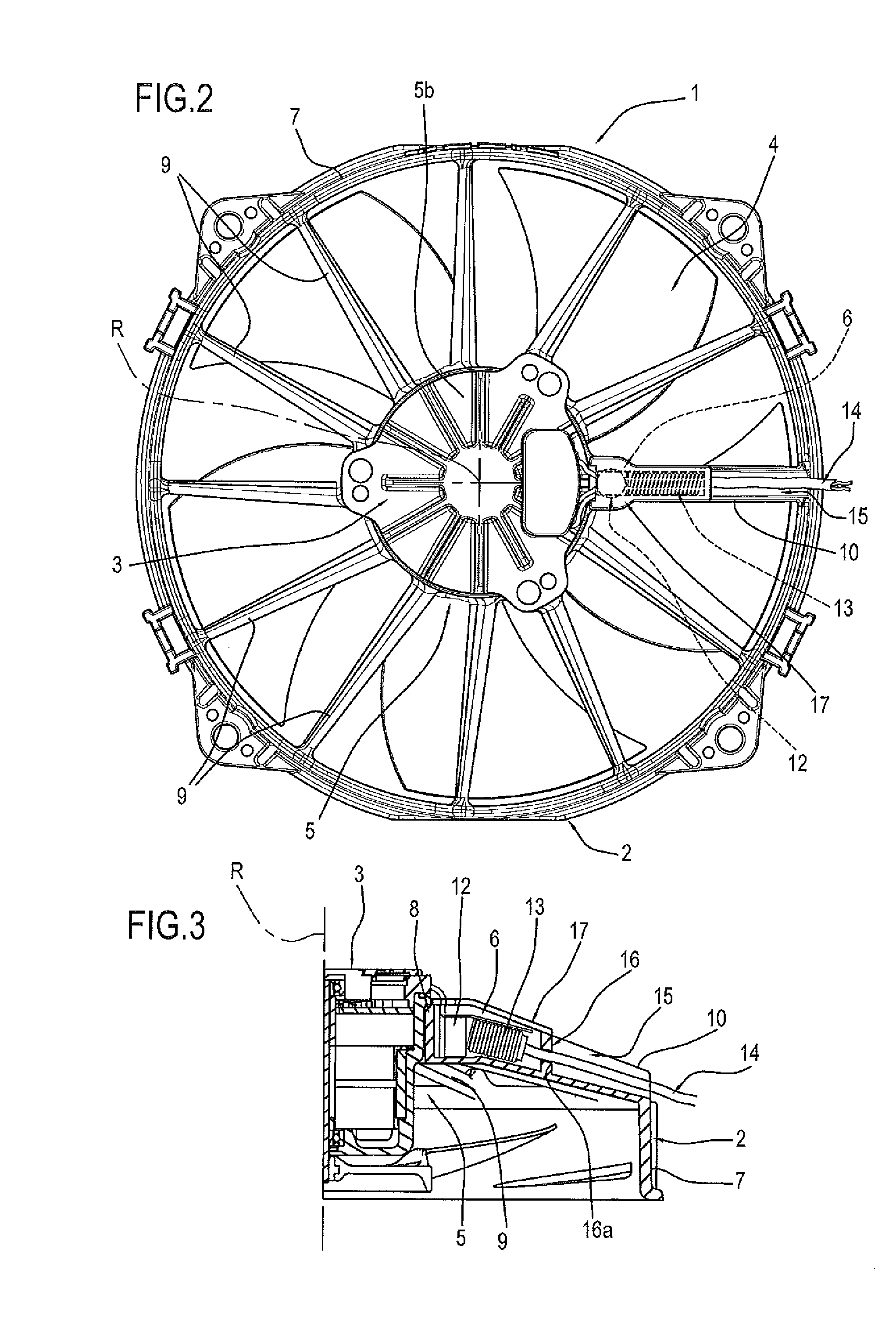
[0020]The electric fan basically comprises an electric motor 3 and an axial fan 4 driven by the electric motor 3 and having an axis of rotation R.

[0021]The electric motor 3, preferably a brushless motor with integrated electronic circuitry, and the fan 4 are described only insofar as necessary for defining and understanding this invention,

[0022]The electric motor 3 which drives the fan 4 comprises a casing 5a, a cap 5b coupled to the casing 5a to form a sealed enclosure 5 and, as mentioned, an electronic system 6 for the selfsame motor 3.

[0023]The electronic system 6 comprises electronic components of substantially known type and is partly housed in the enclosure 5.

[0024]In other words, according to the invention, the electronic control system 6 f...


PUM


Abstract

A ventilation unit includes an axial fan having an axis of rotation; an electric motor for driving the axial fan and comprising a casing, a cap coupled to the casing to form a sealed enclosure and an electronic control system at least partly housed in the enclosure; a shroud supporting the electric motor and having an outer frame for mounting the ventilation unit, an inner collar supporting the electric motor, a plurality of spokes for connecting the inner collar to the outer frame; a first spoke of the shroud comprises a compartment for housing at least one electronic component forming part of the electronic control system.

Description

TECHNICAL FIELD[0001]This invention relates to a ventilation unit and to a shroud forming part of the ventilation unit.[0002]The ventilation unit referred to in this specification is intended mainly for automotive applications, for cooling radiators and the like in motor-cars, lorries or the like.BACKGROUND ART[0003]Recent advances in automotive manufacturing have led to a considerable increase in the number of parts—which occupy more and more space—housed in the engine compartment of vehicles.[0004]Moreover, on account of on-going technological developments, with a view to reducing fuel consumption and vehicle emissions, large quantities of heat need to be removed from the radiant masses in the engine compartments of vehicles.[0005]To this must be added the fact that the engine compartment houses packs of radiators placed one in front of another to perform different functions.[0006]Consider for example that the engine compartment may contain a water radiator, small radiators for th...

Claims


Application Information

Patent Timeline
IPC IPC(8): F04D25/06F01P5/02F04D29/08F04D19/00F04D29/52
CPCF04D25/06F04D19/002F01P5/02F04D29/083F04D29/522F04D25/068F04D25/0693H02K7/14H02K11/33H02K11/02H02K11/026H02K11/028
Inventor DE FILIPPIS, PIETRO
Owner SPAL AUTOMOTIVE
Why Eureka
Try Eureka