
Method, System and Apparatus for Convenience and Compliance with Environmental Protection Regulations and Occupational Safety Standards during On-Site Fluid Flow Meter Calibration and Verification Procedures

Inactive Publication Date: 2015-08-13
GASPARD CRAIG JOSEPH JR
View PDF7 Cites 20 Cited by
  • Summary
  • Abstract
  • Description
  • Claims
  • Application Information

AI Technical Summary

Benefits of technology

This patent proposes a new way to calibrate fluid flow meters that is safer, less invasive, more convenient, more cost-effective, faster, and environmentally friendly. The invention combines several existing techniques to solve problems with current methods, creating a new process for calibrating fluid flow meters.

Problems solved by technology

Although many patented processes and combinations of equipment provide for accurate calibration and verification of fluid flow meters, no existing configurations fully resolve the following problems:1. Interruptions to productivity while the unit under test is moved off-site or while an on-site calibrating expert uses the facility's time and resources for on-site equipment setup2. Limits on the sizes of fluid flow meters that can be calibrated on-site due to limited on-site electrical current and, in turn, limited fluid flow rates obtained during calibration3. Concerns about quality control and cross-contamination among fluid flow meters used in separate divisions of manufacturing4. Improper disposal of hazardous and / or potentially contaminated waste water
Although the components of this system are “modular” and may be disassembled, this configuration is not designed to be used on-site at a manufacturing facility and is not designed to be portable on a daily basis.
As previously noted, this “down time” can last for weeks as the unit is removed from the line of production and subjected to the risks of long-distance shipping.
However, while this method goes far in protecting the flow meters themselves from contamination, the proposal fails to mention any urgency in protecting the environment and, in fact, calls for a connection to an existing “drain pipe,” indicating that the very waste that would be considered contaminating to the meters should be directed into a standard drainage system and released into groundwater.
This same method fails to address the high cost of set-up time at the facility as water tanks are filled and later emptied.
Issues of inconvenience and decreased productivity remain unchallenged by this proposed method of on-site flow meter calibration.
As previously noted, electrical current and voltage available at the typical facility translates into a power supply of up to 2,400 Watts—a level insufficient for the purpose of calibrating fluid flow meters with diameters greater than 2 inches.
In fact, despite the use of the word calibration in the publication's title, no viable method for the adjustment of flow-rate data collection is discussed within the publication's specifications.
Faulty meters cannot be corrected under this arrangement.
Accurate flow rate data collection is therefore potentially compromised, and contamination not only of Master Meters but also of future meters under test becomes an immediate concern.
Because stationary fluid reservoirs at chemical plants or manufacturing facilities and on tanker vehicles alike are large, the attachment of the return line to a space above the liquid level within the reservoir may prove to be challenging and require a great deal of time and effort as massive flow lines are manipulated and connected to existing or non-existing ports atop such reservoirs.
Assembly of the apparatus, therefore, remains a disadvantage to both expert and customer. In contrast, the invention under application allows for the calibrating expert to arrive on-site with a completely set-up, self-contained calibrating system that requires no assembly, and accurate flow meter calibrations may begin within moments of the expert's arrival.(5) Additionally, because under Publication No.
DE20316032 UI would prove nearly impossible to obtain.
Reservoir discharge pumps associated with typical tanker vehicles and large, stationary fluid reservoirs rarely, if ever, contain fluid flow speed controllers, and pumps attached to tanker vehicles and large, stationary fluid reservoirs are not the kind of pumps powerful enough to attain the higher fluid flow rates required for accurate flow meter calibration. Fluid flow meters of larger diameters require higher fluid flow rates during the calibration process.

Method used


Image

  • Method, System and Apparatus for Convenience and Compliance with Environmental Protection Regulations and Occupational Safety Standards during On-Site Fluid Flow Meter Calibration and Verification Procedures
  • Method, System and Apparatus for Convenience and Compliance with Environmental Protection Regulations and Occupational Safety Standards during On-Site Fluid Flow Meter Calibration and Verification Procedures
  • Method, System and Apparatus for Convenience and Compliance with Environmental Protection Regulations and Occupational Safety Standards during On-Site Fluid Flow Meter Calibration and Verification Procedures

Examples


Embodiment Construction

[0043]The present invention employs the comparison of fluid flow meters to standardized Master Meters using the dynamic start-stop reference-meter method as described in —ISO 10790:1999 (E) and as described in other standards relating to the calibration of fluid flow meters.

[0044]This invention proposes a novel configuration of fluid flow meter calibration equipment, providing a combination of solutions to the problems inherent in Existing Methods for fluid flow meter calibration and creating a process for calibrating fluid flow meters that is safe, less invasive, more convenient, more cost-effective, faster and more environmentally friendly.

DETAILED DESCRIPTION OF THE DRAWINGS

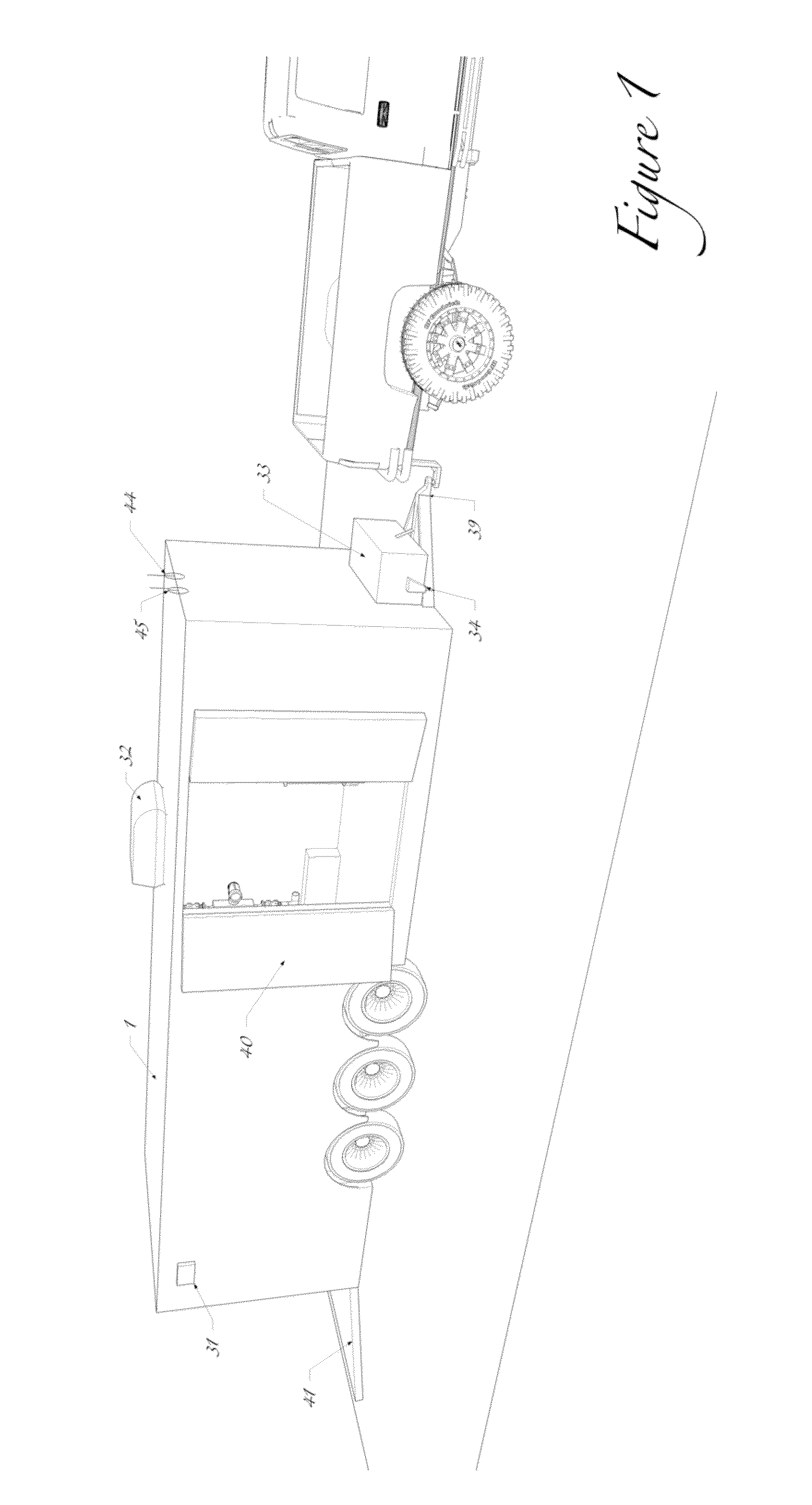
[0045]FIG. 1 depicts a sample configuration of the invention's exterior components.

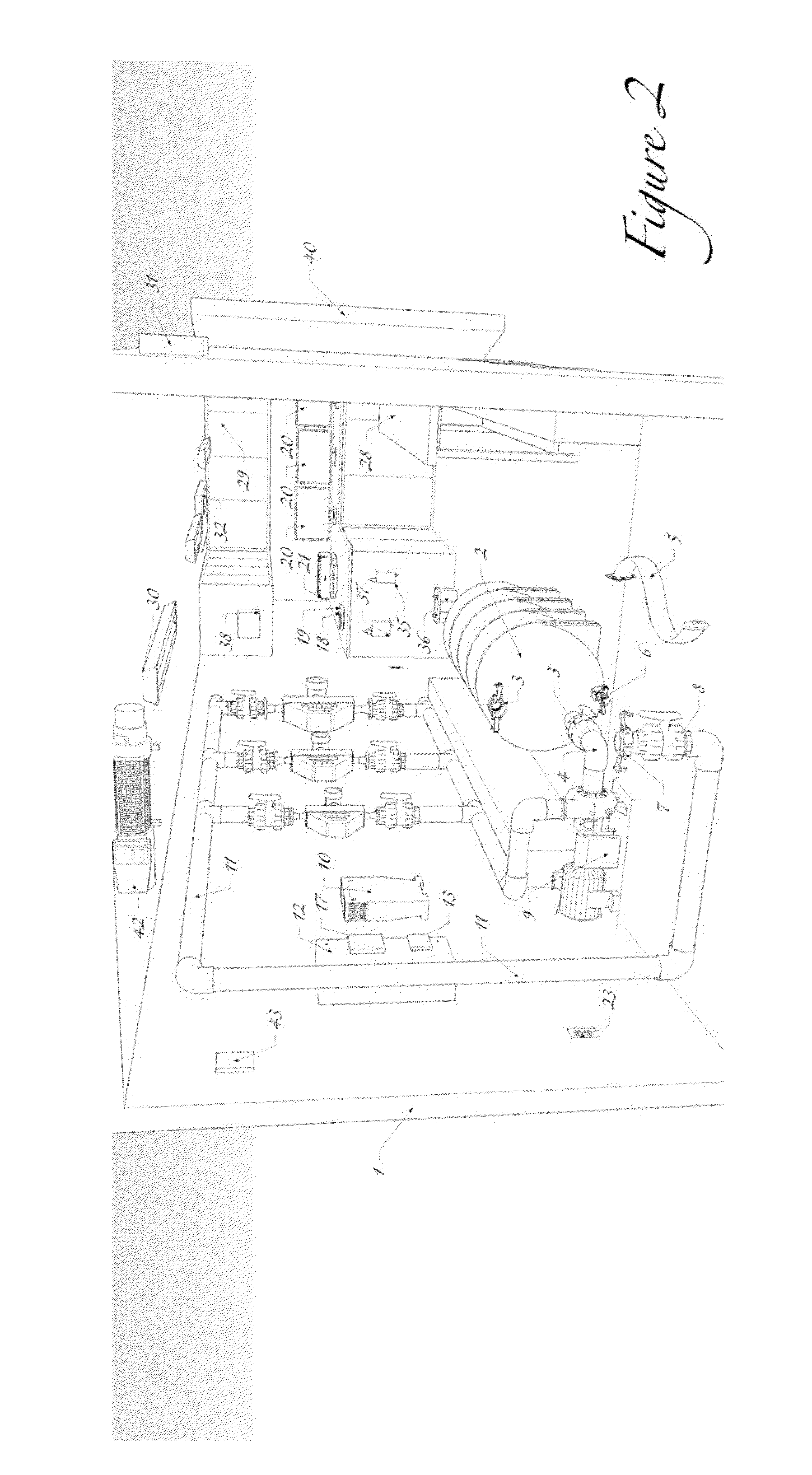
[0046]FIG. 2 depicts a sample configuration of the invention's interior components, as seen from the rear access point.

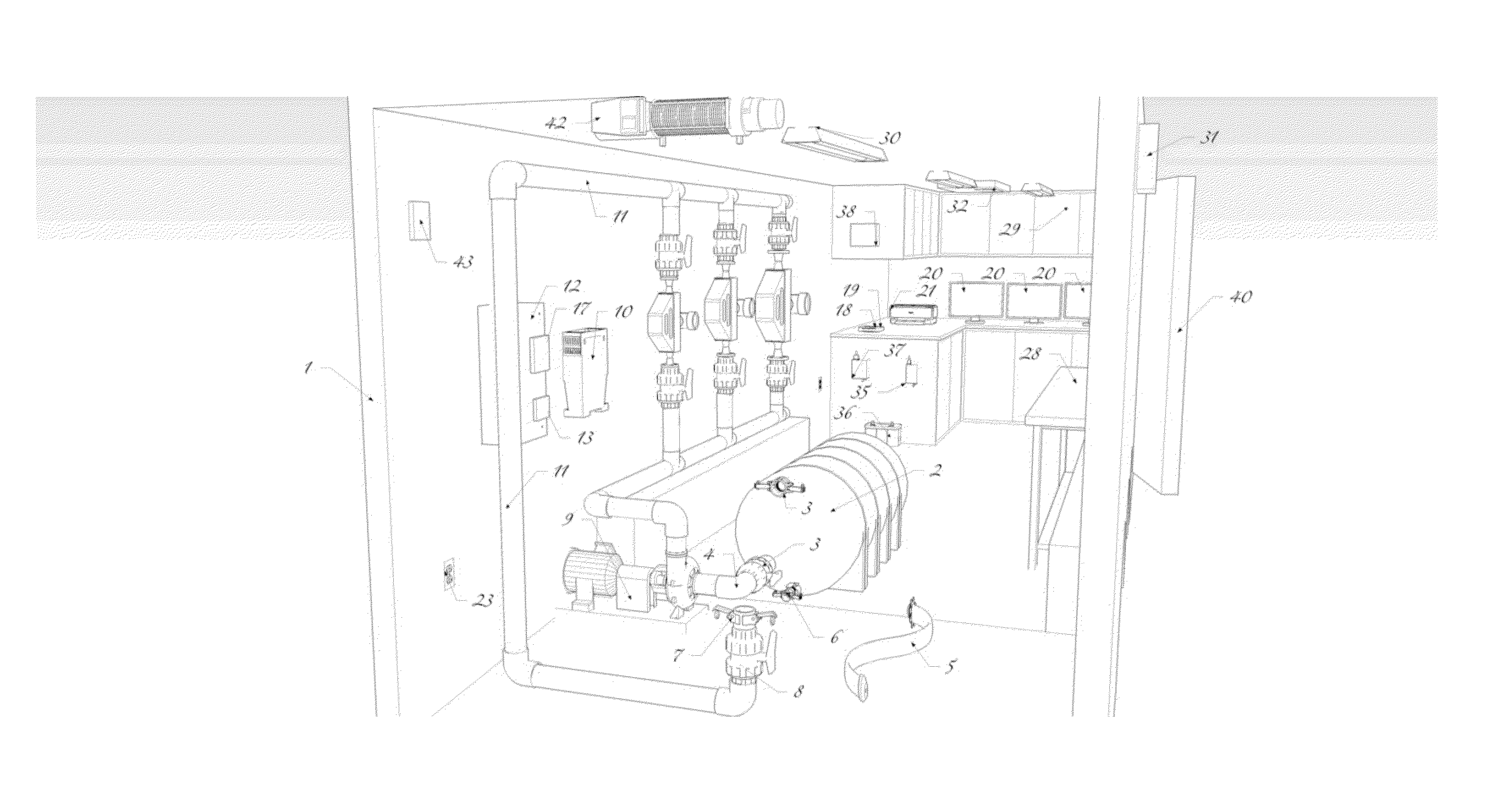
[0047]FIG. 3 depicts a sample configuration of the invention's interior components, as seen from a right-wall...


PUM


Abstract

The present invention offers a useful, novel, and non-obvious means of safely and quickly verifying and calibrating fluid flow instrumentation responsible for the accurate measurement and reporting of various forms of fluid flow rates, including but not limited to the verification and calibration of the fluid flow instrumentation responsible for the measurement and reporting of greenhouse gas emission rates.The present invention introduces major modifications into the field of fluid flow meter calibration and verification and into the field of on-site use of standardized Coriolis flow meters as reference meters (also called “Master Meters”) under procedures such as those set out in the International Organization for Standardization (ISO) Standard No. 10790:1999 (E), for fluid flow meter calibration and verification.The present invention introduces to the field a portable, self-contained system for on-site (field) fluid flow meter calibration and / or verification and eliminates many demands for resources typically placed on manufacturing facilities during fluid flow meter calibration and verification procedures.The present invention includes provision for the convenient and environmentally responsible disposal of contaminated and / or potentially hazardous waste material at authorized locations and thereby creates an atmosphere of enhanced occupational safety for the manufacturing facility requesting on-site fluid flow meter calibrations.

Description

FIELD OF THE INVENTION[0001]This invention addresses the need to verify and accurately calibrate fluid flow meters in a convenient, efficient, safe, cost-effective and environmentally friendly manner.[0002]Because of their ability to measure mass flow and to calculate volumetric flow, Coriolis flow meters are currently used as standard Master Meters during typical on-site and off-site verification and calibration of fluid flow meters. Procedures such as those outlined in the International Organization for Standardization (ISO) Standard No. 10790:1999 (E) are currently employed to ensure accuracy and precision during normal verification and calibration processes.[0003]One impact of this invention on the field is that manufacturing facilities currently compelled to ship fluid flow meters off-site for calibration and verification will have better, more cost-effective options and will no longer be forced to incur the costs, risks and decreased productivity associated with off-site shipp...

Claims


Application Information

Patent Timeline
Patent Type & Authority Applications(United States)
IPC IPC(8): G01F25/00
CPCG01F25/0007G01F1/84G01F25/13G01F25/10
Inventor GASPARD, JR., CRAIG JOSEPH
Owner GASPARD CRAIG JOSEPH JR
Learn More