Reference Voltage Generator for Temperature Sensor with Trimming Capability at Two Temperatures

a temperature sensor and reference voltage technology, applied in the field of temperature sensor circuits, can solve problems such as inaccuracy of temperature sensor outpu

Active Publication Date: 2015-08-13
SANDISK TECH LLC
View PDF7 Cites 15 Cited by
  • Summary
  • Abstract
  • Description
  • Claims
  • Application Information

AI Technical Summary

Benefits of technology

[0003]In a first set of aspects, a temperature sensor circuit includes a temperature dependent voltage section, a reference voltage generation section, a voltage divider section, and an analog to digital converter. The temperature dependent voltage section provides an output voltage having a linear type dependence on temperature. The reference voltage generation section generates a reference voltage, where the level of the reference voltage is trimmable. The voltage divider section is connected to receive the reference voltage from the reference voltage generation section and generate from it a plurality of comparison voltage levels having a first level determined by the reference voltage and a second level dependent upon a first trimmable resistance, the second level being lower than the first. The analog to digital converter is connected to the temperature dependent voltage section to receive the temperature dependent output voltage and connected to the voltage divider section to receive the comparison voltage levels. The analog to digital converter generates an output indicative of the temperature based upon a comparison of the temperature dependent output voltage to the comparison voltage levels.

Problems solved by technology

In practice, such temperature sensors have inaccuracy on their output due to tolerances in manufacturing.

Method used


Image

  • Reference Voltage Generator for Temperature Sensor with Trimming Capability at Two Temperatures
  • Reference Voltage Generator for Temperature Sensor with Trimming Capability at Two Temperatures
  • Reference Voltage Generator for Temperature Sensor with Trimming Capability at Two Temperatures

Examples


Embodiment Construction

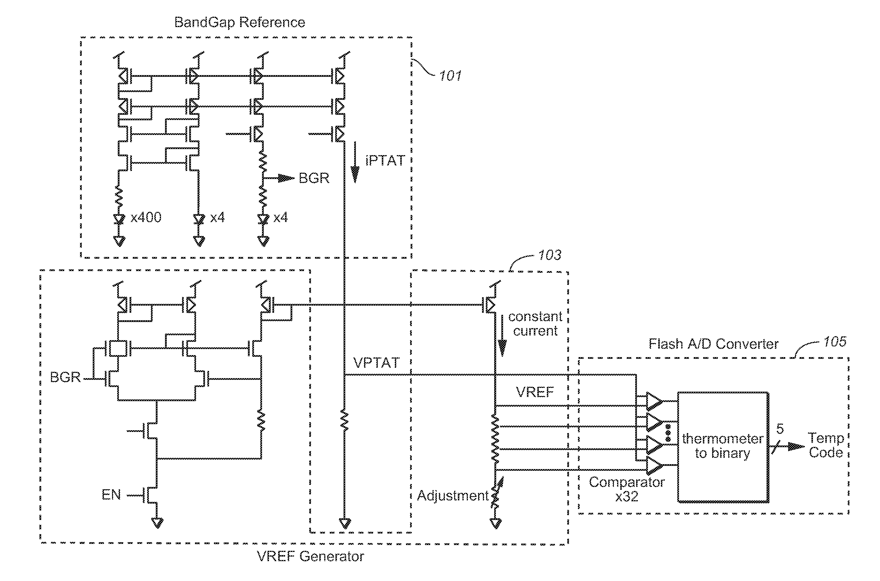
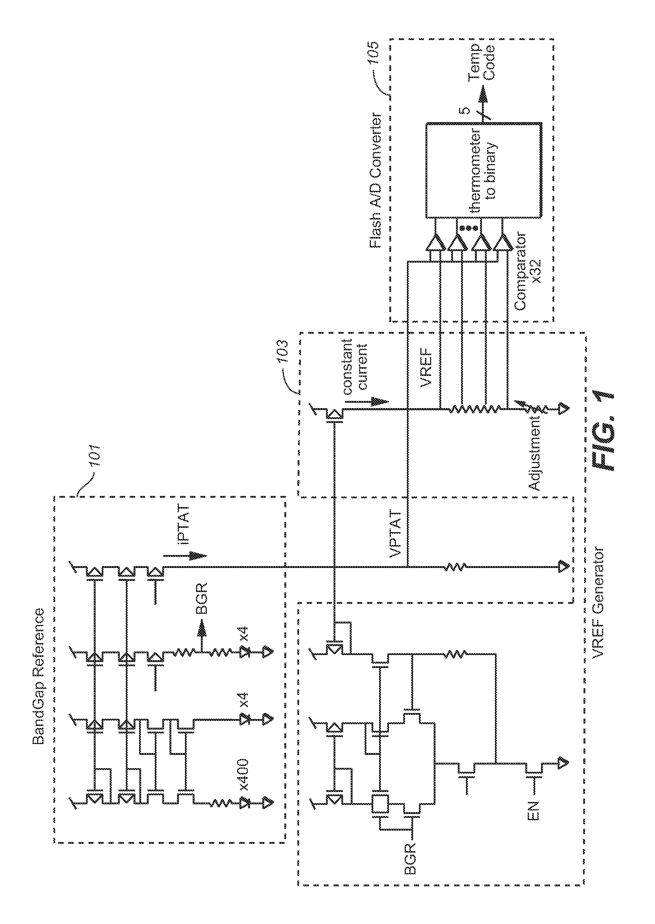
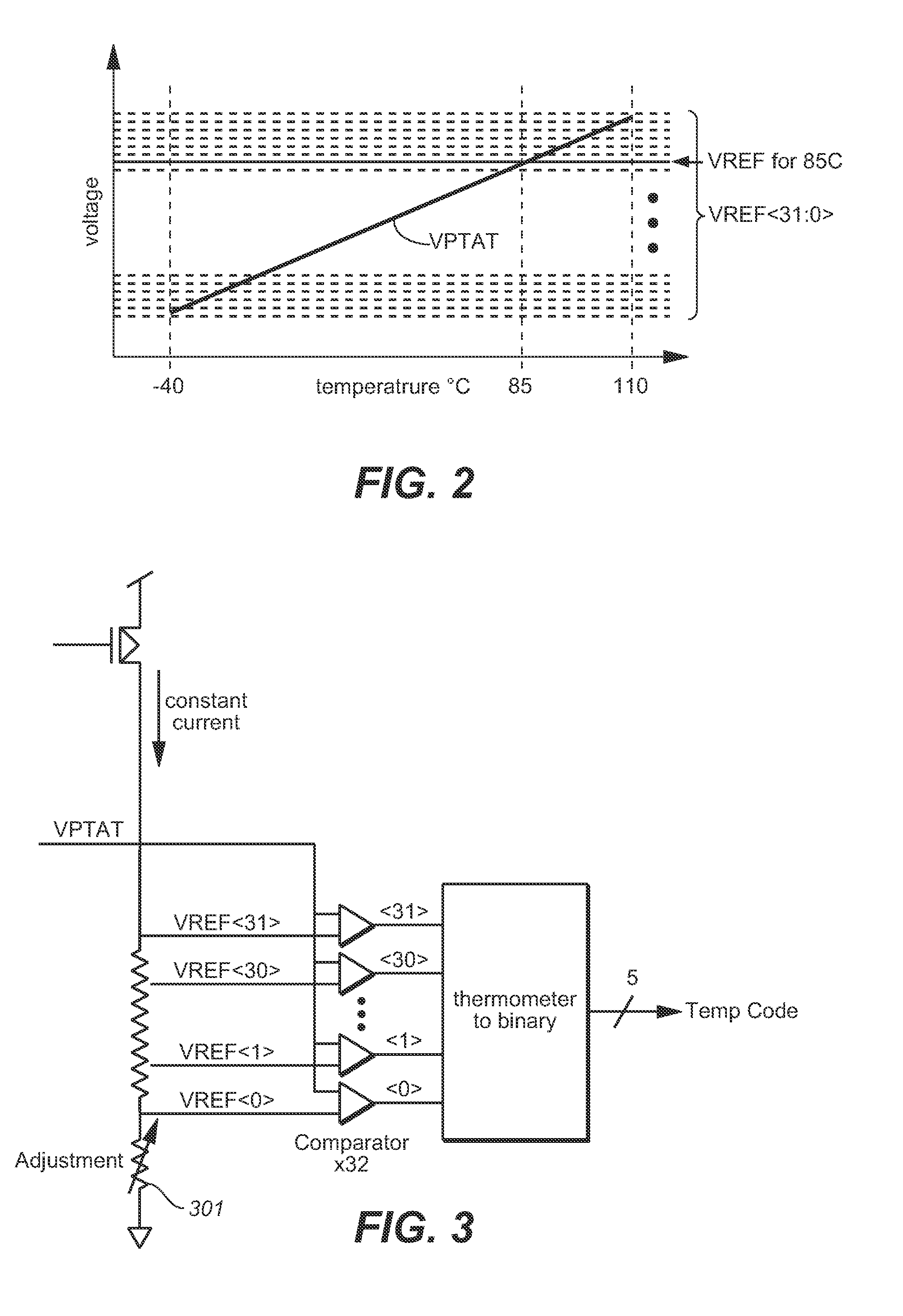
[0012]The following considers temperature code error from temperature sensors and the trimming of such sensors. An example of temperature sensor circuit, such as is shown in FIG. 1, can be constructed using a band gap reference voltage generator section 101, which produces a voltage VPTAT that is proportional to absolute temperature (PTAT), a reference voltage generator section 103, which produces a voltage VREF, that is a temperature-independent reference voltage, and an analogue-to-digital converter (ADC) 105, that compares VPTAT voltage and VREF voltage to produce a digital output (temperature code) at respective temperatures. The number of VREF voltages depends on the number of bits (5 in this example) of ADC, and each VREF voltage corresponds to each temperature level, as shown in FIG. 2.

[0013]FIG. 2 illustrates the desired sort of behavior for the temperature sensor circuit. In this example, the VPTAT rises linearly over the range −40 C to 110 C. The horizontal lines correspon...


PUM

PropertyMeasurementUnit
temperatureaaaaaaaaaa
voltageaaaaaaaaaa
trimmable resistanceaaaaaaaaaa

Abstract

A temperature sensor circuit has a reference voltage generator that is trimmable at two temperatures for increased accuracy. The reference voltage generation section generates a reference voltage, the level of which is trimmable. A voltage divider section is connected to receive the reference voltage from the reference voltage generation section and generate a plurality of comparison voltage levels determined by the reference voltage and a trimmable resistance. An analog-to-digital converter can then be connected to a temperature dependent voltage section to receive the temperature dependent output voltage, such as a proportional to absolute temperature type (PTAT) behavior, and connected to the voltage divider section to receive the comparison voltage levels. The analog to digital converter generates an output indicative of the temperature based upon a comparison of the temperature dependent output voltage to the comparison voltage levels.

Description

FIELD OF THE INVENTION[0001]This invention pertains generally to the temperature sensor circuits and, more particularly, to the trimming of such circuits.BACKGROUND[0002]Temperature sensor circuits can be used as peripheral circuits on devices that use a temperature value or code to adjust their operations. For example, the bias levels on non-volatile memory circuits vary based upon temperature. (For example, the temperature value from a temperature sensor or digital thermometer, such as is described in U.S. Pat. No. 7,889,575 or 8,228,739, is used for bias circuitry on a non-volatile memory circuit.) For accurate operation, the temperature code from such temperature sensors should be accurate. In practice, such temperature sensors have inaccuracy on their output due to tolerances in manufacturing. Consequently, some kind of calibration is necessary in order to correct the output (temperature code).SUMMARY OF THE INVENTION[0003]In a first set of aspects, a temperature sensor circuit...

Claims


Application Information

Patent Timeline
Patent Type & Authority Applications(United States)
IPC IPC(8): G01K7/00H03M1/38G01K13/00
CPCG01K7/00H03M1/38G01K13/00G01K7/01G11C7/04G01K2215/00G01K2219/00G05F3/245H03M1/08G01K15/005G11C16/06H03M1/12H03M7/165
Inventor MATSUMOTO, MASAHIDEYAMASHITA, RYUJI
Owner SANDISK TECH LLC
Why Eureka
Try Eureka