Dual and Triple Axis Inertial Sensors and Methods of Inertial Sensing

a technology of inertial sensing and inertial sensors, applied in the direction of instruments, heat measurement, acceleration measurement in multiple dimensions, etc., can solve the problems of restricting the functionality and practical applicability of the device, correspondingly increasing the cost, size and power requirements of the device, etc., to achieve more accurate determination of acceleration, reduce cross-axis sensitivity, and simplify the processing of the outputs of the sensor

Active Publication Date: 2015-08-13
SILICON MICROGRAVITY LTD
View PDF1 Cites 29 Cited by
  • Summary
  • Abstract
  • Description
  • Claims
  • Application Information

AI Technical Summary

Benefits of technology

[0022]The sensor may comprise a pair of third resonant elements each third resonant element positioned on an opposite side of the proof mass to the other, the third resonant elements being identical to one another, and a pair of second resonant elements each second resonant element positioned on an opposite side of the proof mass to the other, the second resonant elements being identical to one another. By providing identical pairs of resonant elements a differential read out can be used so that frequency fluctuations resulting from environmental factors, such as temperature and pressure variations, can be eliminated from the in-plane acceleration measurement.
[0023]In addition, a common mode read out from one or both pairs of second and third resonant elements can provide an output that is indicative of temperature with a rejection of first order variations in frequency due to acceleration. By taking both the sum (common mode) and difference (differential) read-outs, a multi-parameter sensor is provided. The ability to determine temperature, or changes in temperature, is of interest in many applications in which accelerometers are used. The temperature measurement may also be used in combination with the acceleration read-out to provide a more accurate determination of acceleration. The relationship between resonant frequency and temperature may have second or higher order terms and the temperature measurement can be used to calculate any second order or higher order terms, which are then taken into account when calculating acceleration from the detected resonant frequency shifts.
[0024]The inertial sensor may further comprise a mechanical stage between the proof mass and the frame, the mechanical stage configured to decouple movement of the proof mass in two orthogonal directions in the plane, wherein the second or third resonant elements, or both the second and thi...

Problems solved by technology

However, most of these sensors still remain uniaxial or biaxial, consequently restricting their functionality and practical applicability to those applications that do not demand sophisticated three dimensional (3D) motion control.
Whilst three uniaxial,...

Method used


Image

  • Dual and Triple Axis Inertial Sensors and Methods of Inertial Sensing
  • Dual and Triple Axis Inertial Sensors and Methods of Inertial Sensing
  • Dual and Triple Axis Inertial Sensors and Methods of Inertial Sensing

Examples


Embodiment Construction

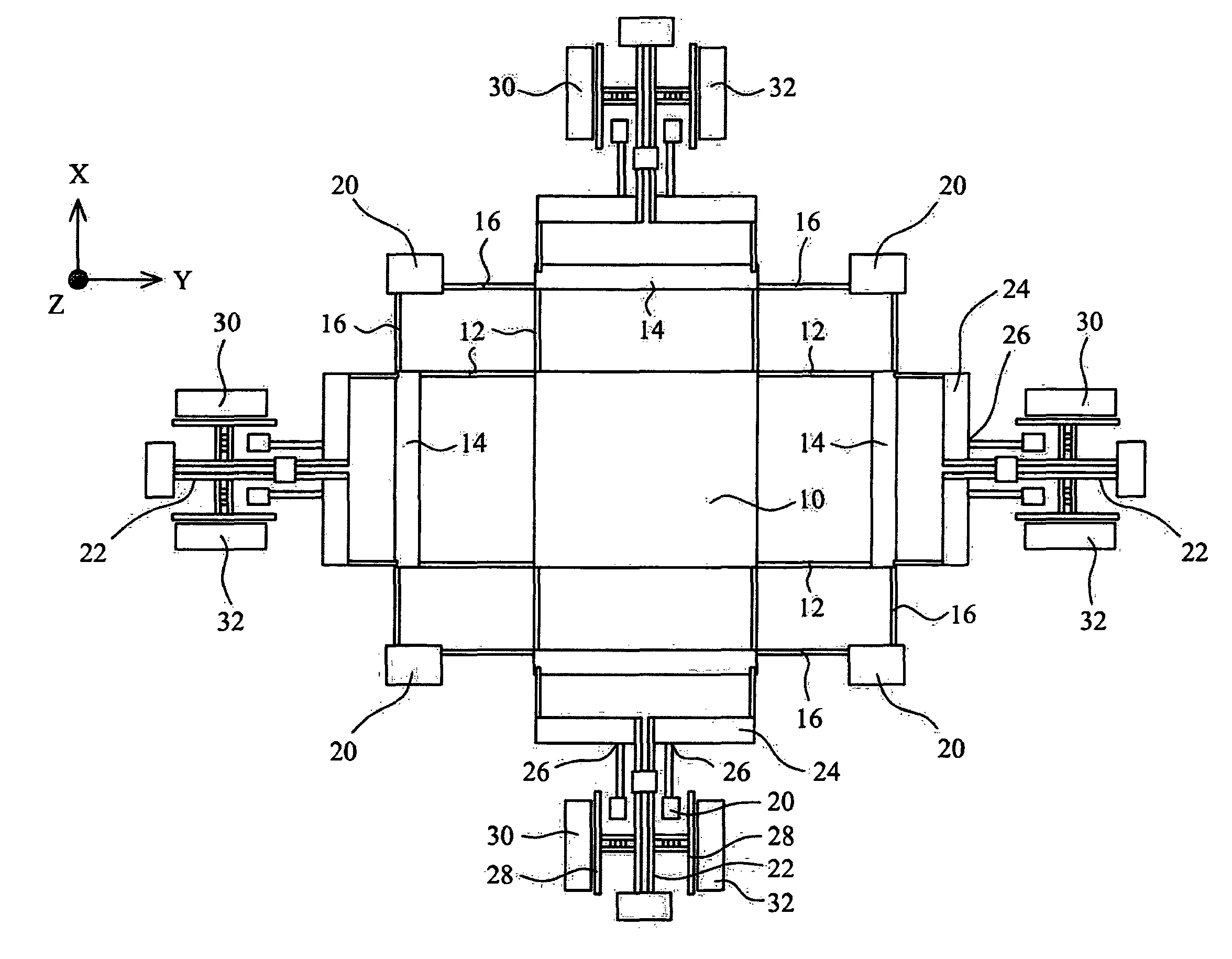
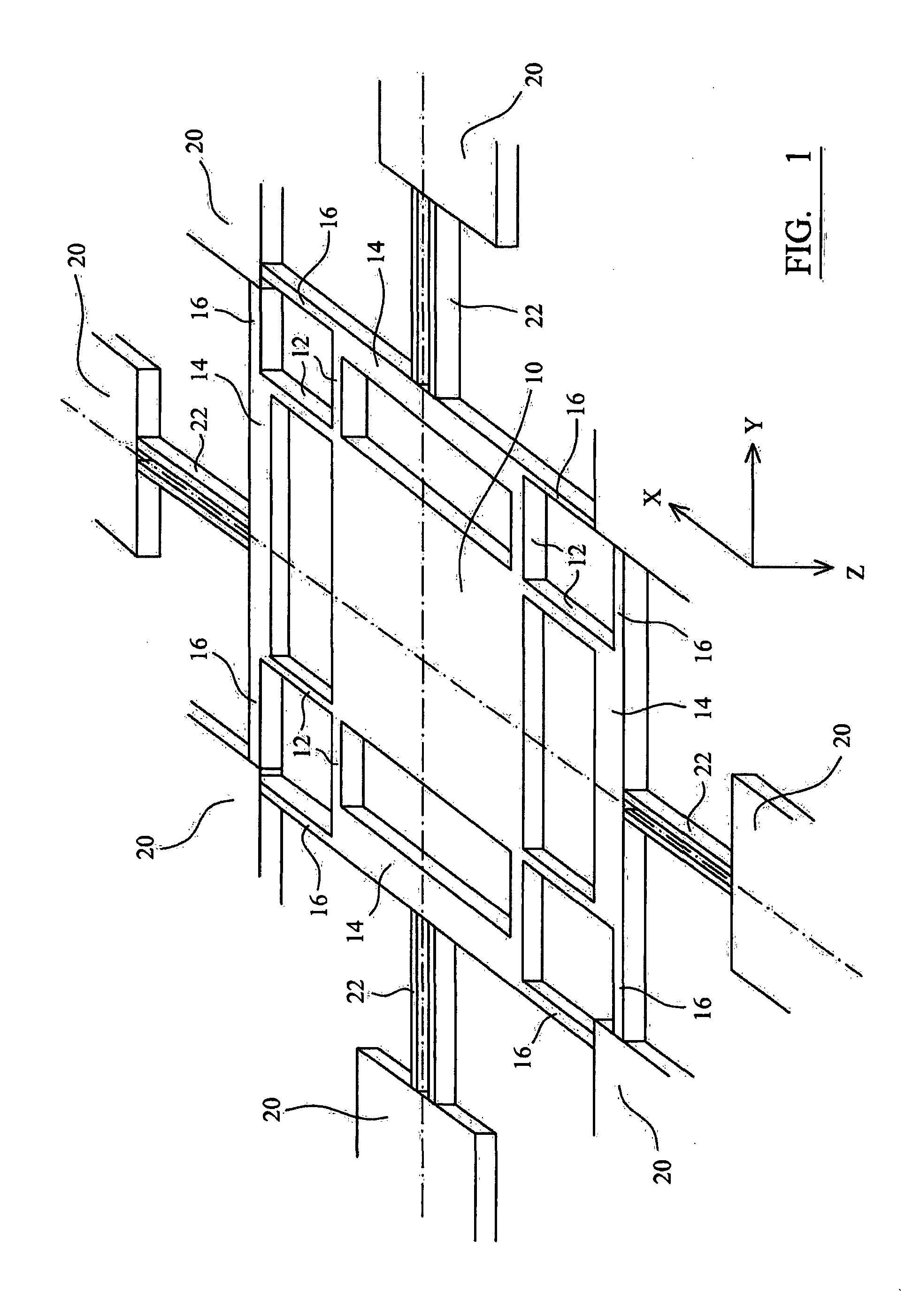
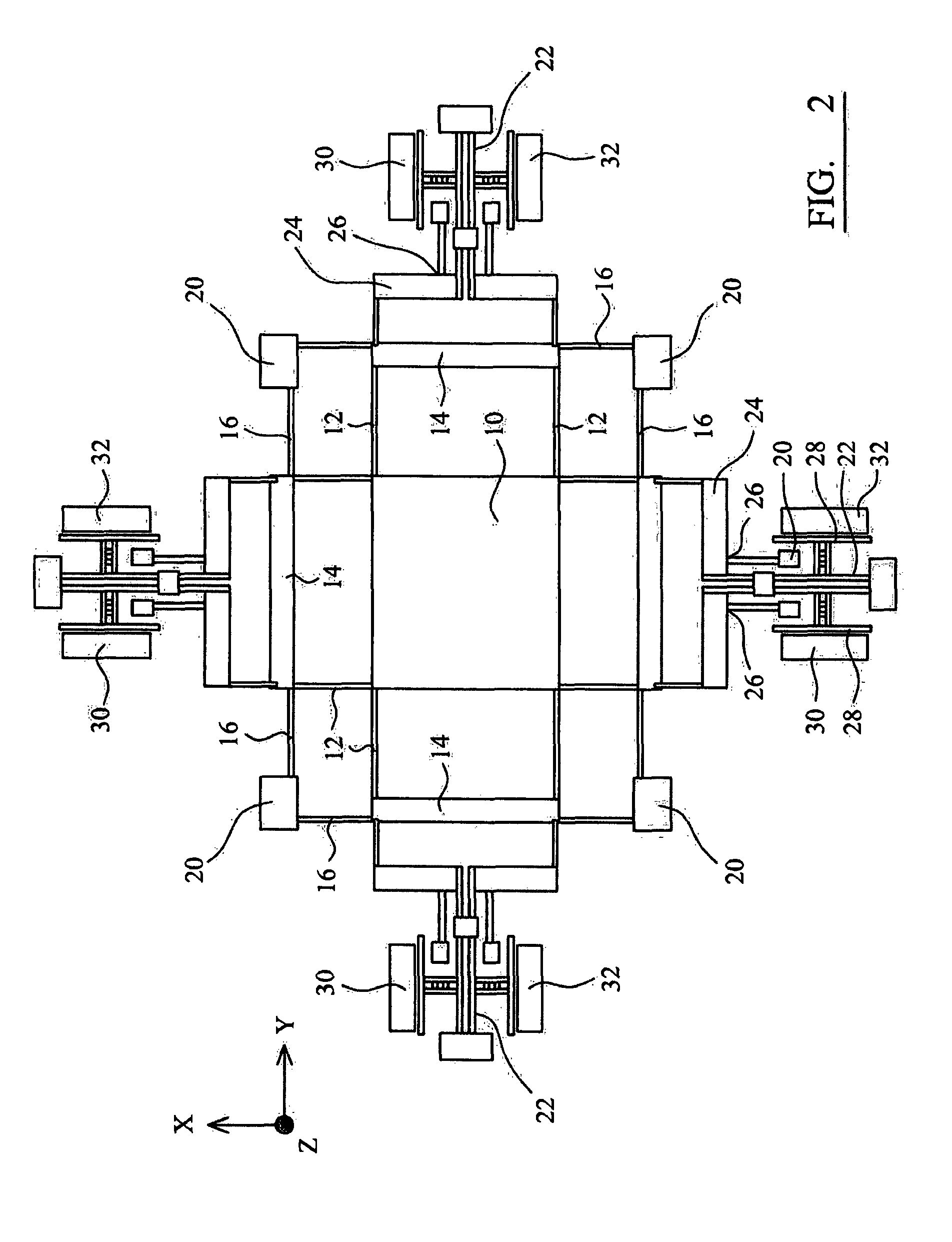
[0065]FIG. 1 is a schematic illustration of a dual axis inertial sensor in accordance with an embodiment of the invention. The sensor comprises a single suspended silicon proof mass held within a dual-axis stage. The dual-axis stage comprises four platforms 14 that are coupled to the proof mass 10 at each corner of the proof mass, by flexures 12. The platforms 14 are coupled to a surrounding frame 20 by flexures 16. The stage is designed in such a way that it allows for decoupled, but symmetric motion of the suspended proof mass in both the X and Y axes, with reduced mechanical cross-talk between the two axes. The stage is designed to restrict the motion of the platforms 14 to one degree of freedom, i.e. along the X or Y axis as shown, while allowing the proof mass suspended within the stage to displace with two degrees of freedom, i.e. along both X and Y axes. This allows decoupled outputs to be connected to the platforms 14 to transduce the acceleration of the proof mass in each o...


PUM


Abstract

An inertial sensor comprising: a frame; a proof mass suspended from the frame; a pair of first resonant elements electrically coupled to the proof mass, or to an intermediate component mechanically coupled to the proof mass, each first resonant element coupled to an opposite side of the proof mass to the other, the first resonant elements being substantially identical to one another and having substantially identical electrostatic coupling with the proof mass when the sensor is not accelerating; wherein the first resonant elements and proof mass lie substantially in a plane, and wherein movement of the proof mass relative to the first resonant elements orthogonal to the plane alters the electrostatic coupling between the proof mass and the first resonant elements; drive means coupled to the first resonant elements for vibrating each of the first resonant elements; and a sensor assembly for detecting a shift in the resonant frequency of each of the first resonant elements; and processing means for summing the shifts of each of the first resonant elements to provide a measure of acceleration of the proof mass parallel to a first axis, the first axis being orthogonal to the plane.

Description

FIELD OF THE INVENTION[0001]The present invention relates to inertial sensors and methods of inertial sensing using microscopic mechanical inertial sensors. In particular, the invention relates to inertial sensors that can be readily manufactured and are capable of sensing in two or three orthogonal directions using only a single suspended proof mass.BACKGROUND TO THE INVENTION[0002]Oscillators based on lightly damped microscopic mechanical resonators are well known for their ability to produce stable, low-noise frequency outputs. While these characteristics make them valuable in communication systems as stable timing frequency references, they also make them attractive for use as sensors. A resonant sensor, by definition, is an oscillator whose output frequency is a function of an input measurand. In other words, the output of a resonant sensor corresponds to the shift in resonant frequency of a mechanical microstructure that gets tuned in accordance to a change in a physical chemi...

Claims


Application Information

Patent Timeline
IPC IPC(8): G01P1/00G01K11/26G01P15/097
CPCG01P1/006G01K11/26G01P15/097G01K7/32G01P15/18G01P2015/084G01P15/0802G01P15/125
Inventor SESHIA, ASHWIN ARUNKUMARTHIRUVENKATANATHAN, PRADYUMNAZOU, XUDONG
Owner SILICON MICROGRAVITY LTD
Why Eureka
Try Eureka