System for insulating an induction vacuum furnace and method of making same

a vacuum furnace and vacuum furnace technology, applied in the field of vacuum furnaces, can solve the problems of affecting the operating efficiency of the furnace and the temperature uniformity within the furnace, affecting the efficiency of the furnace and the furnace, and the induction coils of the furnace tend to be affected by dielectric breakdown, so as to prevent dielectric breakdown around the induction coils, the effect of efficient and uniform heating

Inactive Publication Date: 2015-08-13
GH INDUCTION ATMOSPHERES +1
View PDF7 Cites 6 Cited by
  • Summary
  • Abstract
  • Description
  • Claims
  • Application Information

AI Technical Summary

Benefits of technology

[0006]It would therefore be desirable to design an induction furnace capable of operating at temperatures above 1200 degrees Celsius, while maintaining efficient and uniform heating and preventing dielectric breakdown around the induction coils.

Problems solved by technology

Prior art induction furnaces experience a number of negative effects when operating at temperatures above 1200 degrees Celsius.
For example, the operating efficiency of the furnace and the temperature uniformity within the furnace is negatively affected.
Further, dielectric breakdown tends to occur around the induction coils of the furnace at furnace operating temperatures above 1200 degrees Celsius.

Method used


Image

  • System for insulating an induction vacuum furnace and method of making same
  • System for insulating an induction vacuum furnace and method of making same
  • System for insulating an induction vacuum furnace and method of making same

Examples


Embodiment Construction

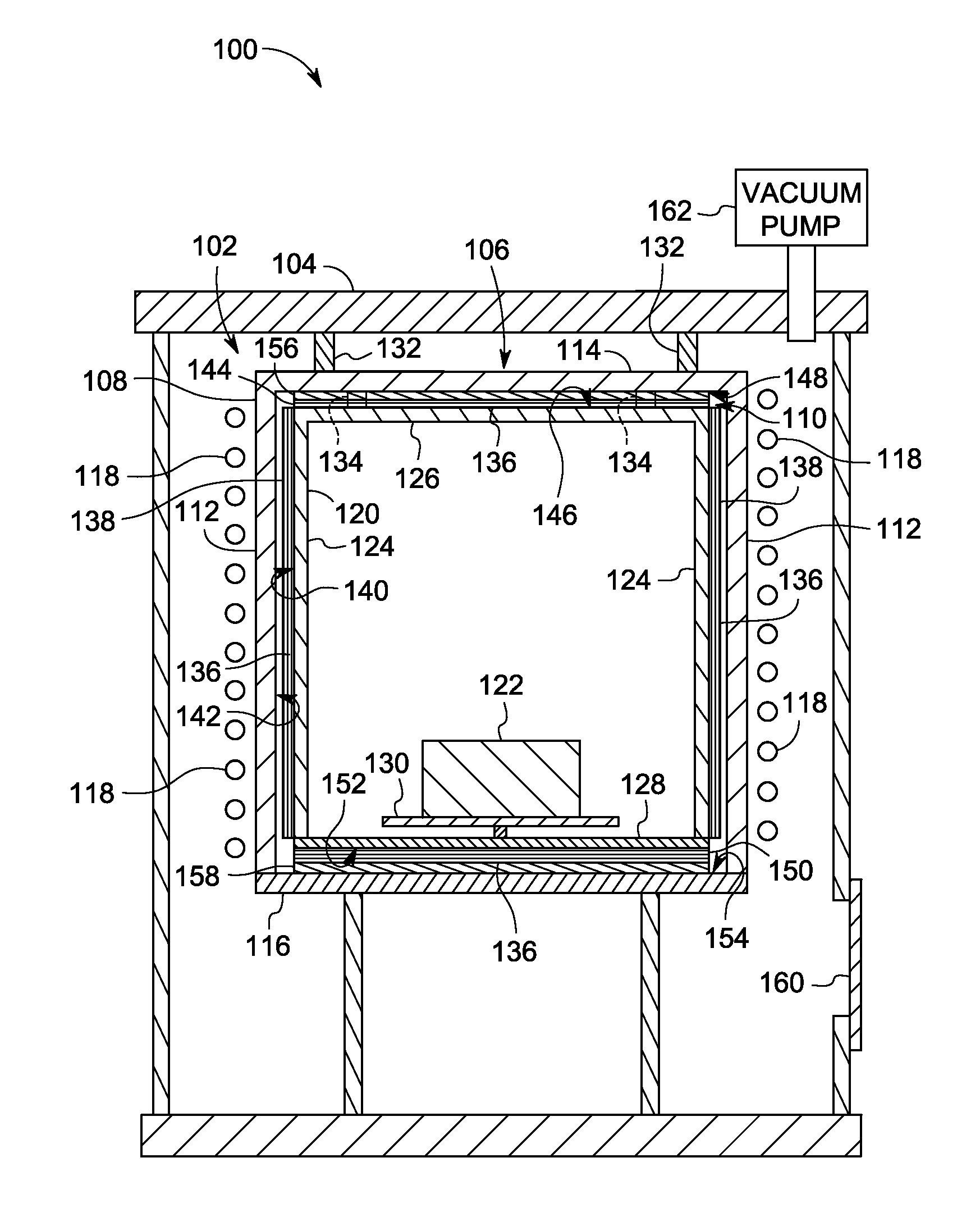
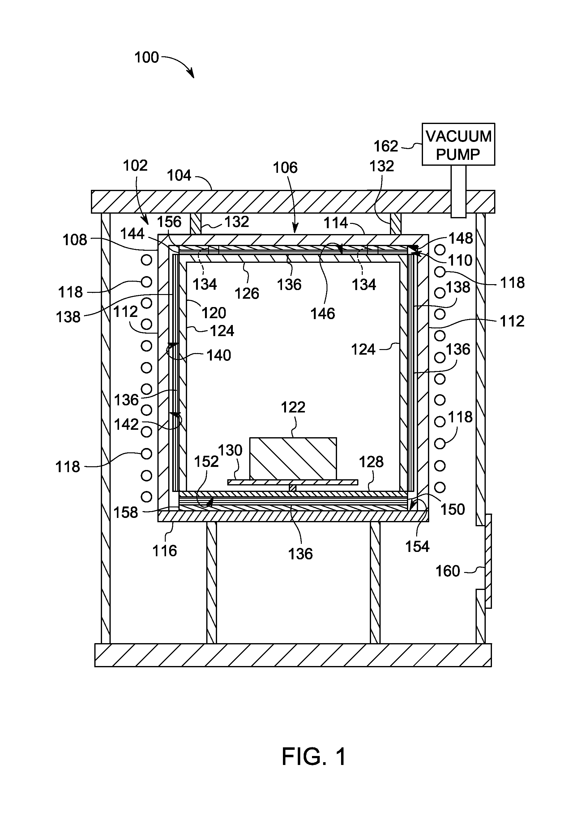
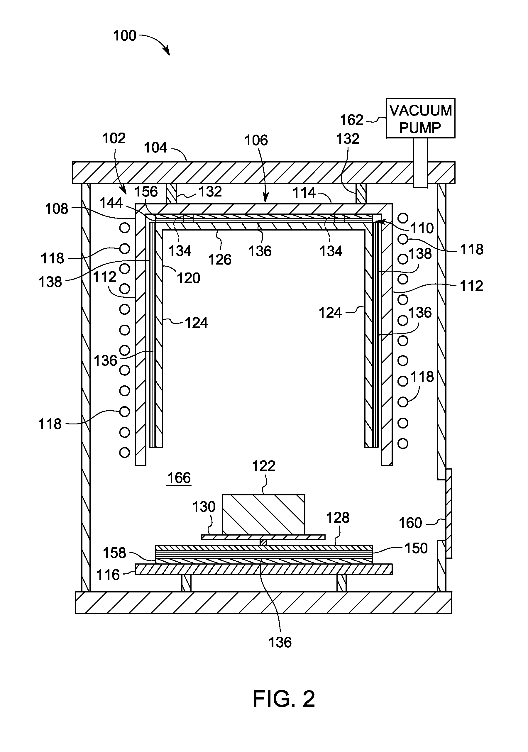
[0020]Referring to FIGS. 1 and 2, the major components of an induction furnace 100 are shown. Induction furnace 100 includes an induction heating system 102 inside a chamber 104. Induction heating system 102 includes an insulation package 106 comprising an insulation cylinder 108 and an insulating jacket assembly 110. Insulation cylinder 108 includes a side wall 112, a first cover 114 for sealing one end of cylinder 108, and a second cover 116 for sealing the second end of cylinder 108. Induction heating system 102 includes a coil 118 and a power supply (not shown) that provides an alternating current that flows through coil 118 during a heating cycle. Coil 118 is wound to form a helical shape within chamber 104 about insulation cylinder 108 as shown in FIG. 1.

[0021]Contained within insulation cylinder 108 is a susceptor 120 that is susceptible to induction heating. That is, when an alternating current flows through coil 118, an alternating magnetic field is generated that induces e...


PUM

PropertyMeasurementUnit
temperaturesaaaaaaaaaa
temperatureaaaaaaaaaa
operating temperaturesaaaaaaaaaa

Abstract

A system and method for insulating an induction vacuum furnace is disclosed. An induction furnace for heating a workpiece includes a chamber, an insulation cylinder positioned within the chamber, and an induction coil positioned to surround at least a portion of the insulation cylinder. A susceptor is positioned within the insulation cylinder and inductively heated by the induction coil when a current is provided to the induction coil. An insulating jacket assembly including one of a carbide material and a refractory metal is positioned in a space between the insulating cylinder and the susceptor.

Description

CROSS-REFERENCE TO RELATED APPLICATION[0001]This is a national stage application under 35 U.S.C. §371(c) of prior-filed, co-pending, PCT application serial number PCT / US2013 / 038796, filed on Apr. 30, 2013, which claims priority to U.S. Provisional Application No. 61 / 694,869, filed Aug. 30, 2012, the contents of which are incorporated herein by reference.BACKGROUND OF THE INVENTION[0002]Embodiments of the invention relate generally to induction furnaces for heating a workpiece in an inert atmosphere or vacuum and, more particularly, to a system for providing an insulation package for an induction furnace having improved insulation properties at temperatures above 1200 degrees Celsius.[0003]Conventional induction furnaces include an induction heating system and a chamber that contains a susceptor that is susceptible to induction heating, with the chamber enclosing an inert atmosphere or vacuum therein. An electromagnetic coil sits outside the susceptor and receives high frequency alte...

Claims


Application Information

Patent Timeline
Patent Type & Authority Applications(United States)
IPC IPC(8): H05B6/10H01F5/02F27D11/06F27B5/04F27B5/14
CPCH05B6/105F27B5/04F27B2005/062F27D11/06H01F5/02F27B5/14F27B14/04B23P19/00F27B14/061F27B14/08F27B2014/045F27B2014/066F27B2014/0831F27B2014/0837F27B2014/0887F27D7/06F27D9/00F27D2009/0075F27D2021/0078H05B6/26Y10T29/4902Y10T29/49826
Inventor STEINLAGE, GREGORY ALANSZUGYE, MICHAEL LOUISPOQUETTE, BEN DAVIDVANSUMMEREN, MARK ANDREWWILCOX, DALE R.COSTANTINO, PETER M.TUMIA, TIMOTHY C.DALLICARDILLO, GIOVANNI A.
Owner GH INDUCTION ATMOSPHERES
Why Eureka
Try Eureka