Steerable Medical Device Handle

Active Publication Date: 2015-08-20
BOSTON SCI MEDICAL DEVICE LTD
View PDF6 Cites 23 Cited by
  • Summary
  • Abstract
  • Description
  • Claims
  • Application Information

AI Technical Summary

Benefits of technology

[0004]In one broad aspect, embodiments of the present invention provide a control system for bi-directional control of a steerable catheter, the catheter including at least two control wires, a distal end of each of the control wires being coupled to the catheter at a distal region thereof, the control system comprising: a housing coupled to the catheter; a slide assembly positioned within the housing and operable to translate linearly therein; a proximal portion of each of the at least two control wires being mounted or positioned through the slide assembly; and a control knob rotatably coupled to the housing for linearly translating the slide assembly, thereby enabling the slide assembly to separately manipul

Problems solved by technology

However, the slider mechanism disclosed by Falwell lacks ease of use as it is awkward to grasp and use.
Furthermore, the disclosed slider mechanism provides limited control in steering the catheter.
The device provides a thumb control that lacks precision.
It is unable to provide precise steering of the catheter as it lacks resolution for permitting minute manipula

Method used


Image

  • Steerable Medical Device Handle
  • Steerable Medical Device Handle
  • Steerable Medical Device Handle

Examples


example 1

Slide Limiting Element is the Track

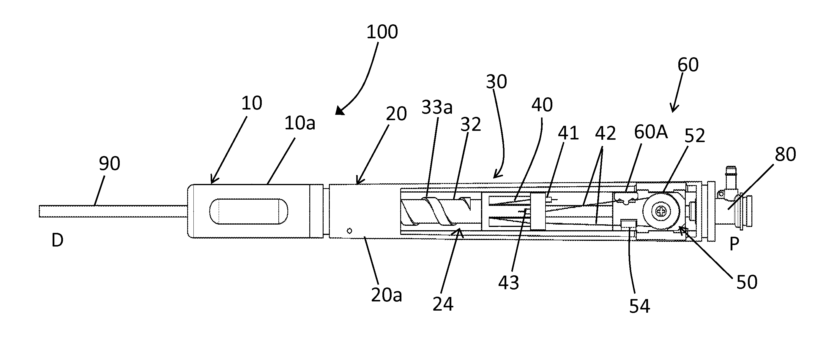
[0103]As outlined above, the track 21a within the inner housing 20a can additionally function as a slide stop to restrict the movement of the slide assembly 30 to allow for a desired deflection of the sheath 90. As shown in FIG. 10a, once the slide assembly 30 (for example a raised projection 31a of the slide assembly 30 shown in FIG. 3E) reaches the end of the track it abuts against a wall 21a′ at the end of the groove or track 21a, thereby stopping or limiting linear motion of the slide assembly.

[0104]In some embodiments, the length of the track 21a may be adjustable to alter the degree of deflection that may be provided in the sheath 90 using the handle 100. Thus in some embodiments a shorter track 21a may be provided in the inner housing 20a as shown in FIG. 10a, providing a shorter translation distance for the slide assembly 30 resulting in a more limited range of motion for the sheath 90. In other words the sheath 90 is provided with a reduce...

example 2

Slide Limiting Element is a Tubular Slide Stop

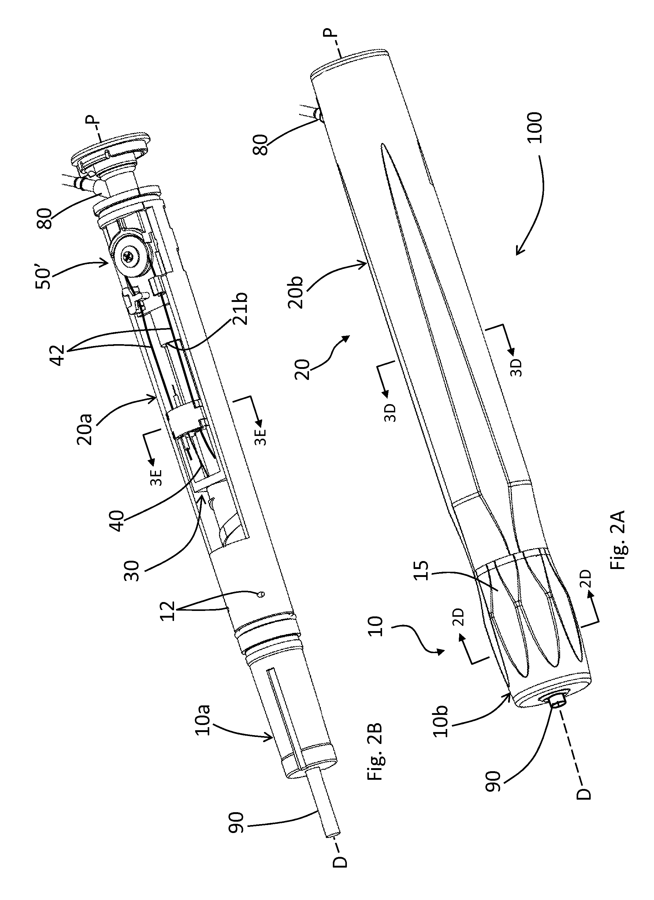
[0106]In some embodiments as described previously, the slide limiting element comprises a tubular slide stop 21b as shown in FIGS. 2A-2C, 4B-4C, 5A and 10D. The use of a longer tubular slide stop 21b results in a more restricted movement of the slide assembly 30. In one example, the tubular slide stop 21b is positioned proximal to the slide assembly 30. In some embodiments the tubular stop 21b comprises a relatively hard material and is substantially rigid such that it does not yield substantially under application of force. In one such example, upon clockwise rotation of the knob 10, as slide assembly 30 translates proximally within the inner housing 20a the slide assembly 30 abuts against the wall 21b′ of a rigid tubular slide stop 21b preventing further translation of the slide assembly 30. This provides tactile feedback which may be experienced as a hard stop by the user. This may help indicate to the user that the maximum deflection...

example 3

Slide Limiting Element Comprises a Bar

[0108]As described previously, in some embodiments the slide limiting element or slide stop comprises a bar 21c extends with the inner housing 20a along a transverse plane. In one example, the bar 21c is positioned between the slide assembly 30 and the pulley assembly 50. The bar 21c impedes or restricts the movement of the slide assembly 30 as it abuts against wall 21c′ of the bar, thus restricting the total translation distance available to the slide assembly 30. This consequently restricts the amount of tension that can be placed on one or more of the wires 40, 42 and thus limiting the deflection of the sheath 90.


PUM


Abstract

A control system and method are provided for control of a steerable catheter, the catheter including at least two control wires, a distal end of each of the control wires being coupled to the catheter at a distal region thereof, the control system comprising: a housing coupled to the catheter; a slide assembly positioned within the housing and operable to translate linearly therein; a proximal portion of each of the at least two control wires being positioned through the slide assembly; and a control knob rotatably coupled to the housing for linearly translating the slide assembly, thereby enabling the slide assembly to separately manipulate each of said at least two control wires to effect a change in a deflection of said catheter. Rotation of the control knob in a first rotational direction causes distal movement of the slide assembly in a first linear direction causing the slide assembly to tension one of said at least two control wires thereby effecting a change in the deflection of said catheter in a first deflection direction and wherein rotation of the knob in a second rotational direction causes proximal movement of the slide assembly in a second linear direction causing the slide assembly to tension the other of said at least two control wires thereby effecting a change in the deflection of said catheter in a second deflection direction.

Description

TECHNICAL FIELD[0001]The disclosure relates to a handle for a medical device. More specifically the disclosure relates to a handle for a medical device that enables steering of the medical device in the body.BACKGROUND OF THE ART[0002]U.S. Pat. No. 5,944,690 granted to Falwell et al. discloses a steerable catheter control mechanism for manipulating a pair of control wires which utilizes a slider mechanism coupled to the proximal ends of the control wires. However, the slider mechanism disclosed by Falwell lacks ease of use as it is awkward to grasp and use. Furthermore, the disclosed slider mechanism provides limited control in steering the catheter. The device provides a thumb control that lacks precision. It is unable to provide precise steering of the catheter as it lacks resolution for permitting minute manipulations needed to provide slight changes in the deflection of the catheter.[0003]U.S. Pat. No. 7,691,095 granted to Bednarek et al. discloses a bi-directional steerable cat...

Claims


Application Information

Patent Timeline
IPC IPC(8): A61M25/01
CPCA61M25/0147A61M25/0136
Inventor DAVIES, GARETHTHOMPSON, MELANIEGORAPALLI, DEEPTHICOPELAND, STEVEDICKIE, ROBERT G.LEFLER, AMYBECA, BOGDAN
Owner BOSTON SCI MEDICAL DEVICE LTD
Why Eureka
Try Eureka