Motor control device, motor control method, and blower apparatus

a motor control device and motor control technology, applied in general control strategies, mechanical devices, machines/engines, etc., can solve the problems of inability to maintain air flow at a constant value, inability to easily install pressure sensors, and change in pressure loss condition with time, so as to achieve fewer experiment steps and high accuracy

Active Publication Date: 2015-08-20
PANASONIC INTELLECTUAL PROPERTY MANAGEMENT CO LTD
View PDF41 Cites 14 Cited by
  • Summary
  • Abstract
  • Description
  • Claims
  • Application Information

AI Technical Summary

Benefits of technology

[0020]The present invention is configured as described above, and has an advantage that it becomes possible to implement constant air flow co...

Problems solved by technology

Also, due to clogging of a filter attached to the outlet port or suction port of the air conditioning apparatus, the pressure loss condition changes with a passage of time.
Or, even when a particular air conditioning apparatus is d...

Method used


Image

  • Motor control device, motor control method, and blower apparatus
  • Motor control device, motor control method, and blower apparatus
  • Motor control device, motor control method, and blower apparatus

Examples


embodiment 1

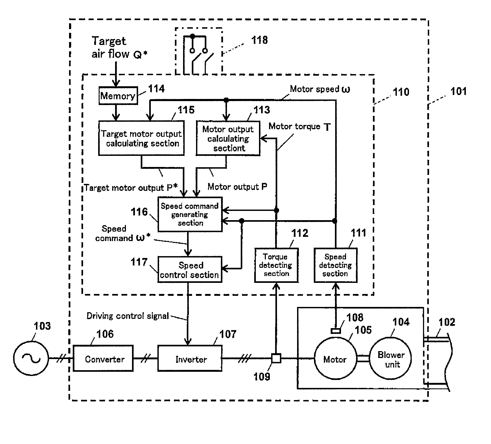
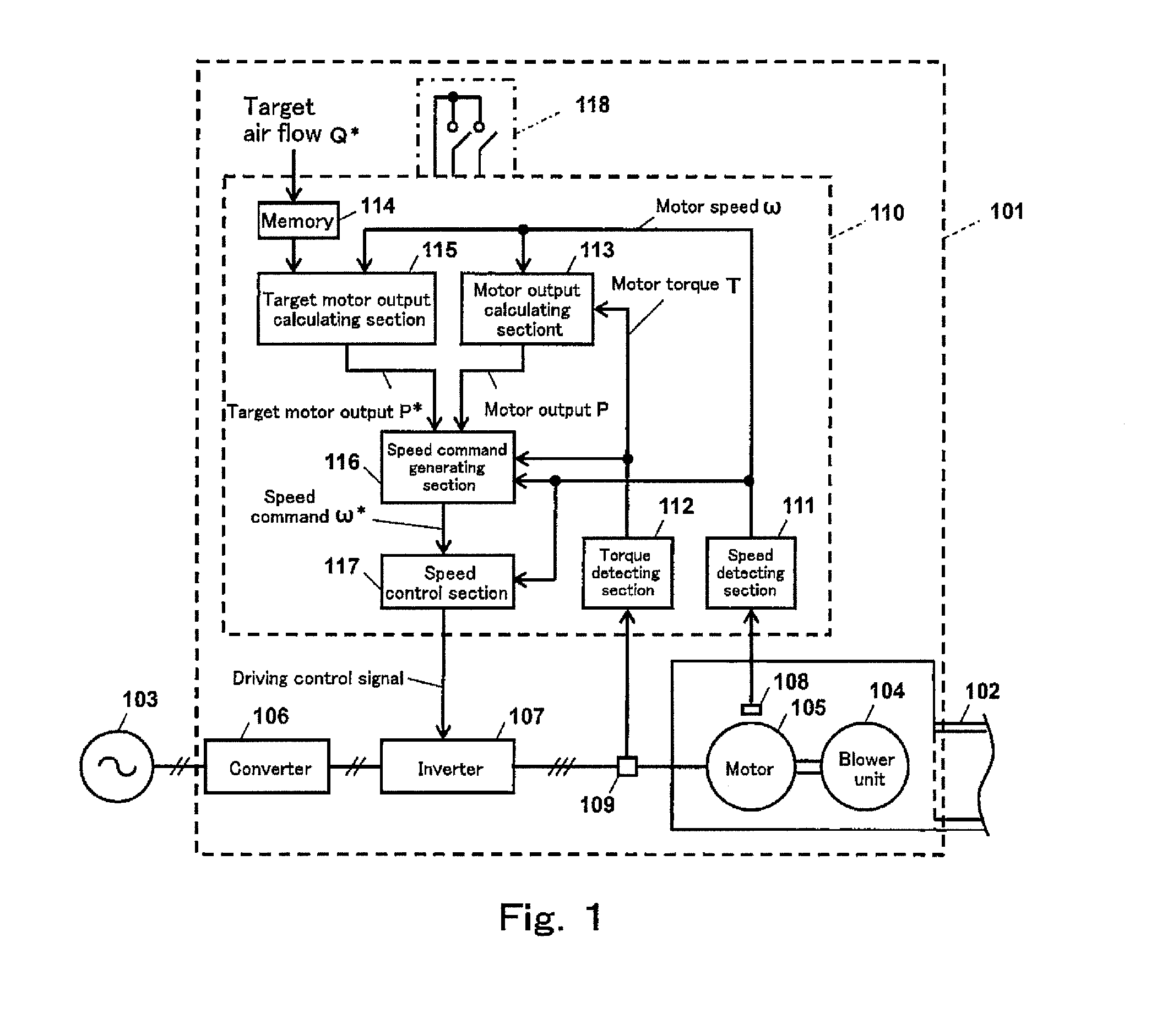
[0102]FIG. 1 is a block diagram showing an air conditioning apparatus to which a motor control device according to Embodiment 1 of the present invention is applied. As shown in FIG. 1, an air conditioning apparatus 101 configured as a blower apparatus of the present embodiment includes a blower unit 104 which sends air to an air flow passage 102, a motor 105 which drives the blower unit 104, a converter 106 which converts AC power supplied from an AC power supply 103 into DC power, an inverter 107 which converts the DC power into the AC power and supplies the AC power to the motor 105, a position detector 108 which detects the position of a rotor (not shown) of the motor 105, a current detector 109 which detects the current of the motor 105, and a motor control device 110 which controls the air flow of the air conditioning apparatus 101 such that the air flow coincides with a target air flow Q*.

[0103]The motor control device 110 includes a speed detecting section 111 which detects a...

embodiment 2

[0150]Hereinafter, a motor control device according to Embodiment 2 of the present invention will be described. FIG. 5 is a block diagram showing the motor control device according to Embodiment 2 of the present invention. As shown in FIG. 5, Embodiment 2 is different from Embodiment 1 in that the speed command generating section 116 and the speed control section 117 of Embodiment 1 are replaced by a torque command generating section 516 and a torque control section 517. The other components are identical to those of Embodiment 1. Therefore, they are designated by the same reference symbols and will not be described repeatedly.

[0151]The operations of the torque command generating section 516 and of the torque control section 517 in the motor control device 510 of FIG. 5 will be described.

[0152]The torque command generating section 516 generates a torque command T* for controlling the motor torque T of the motor 105 so that the motor output P coincides with the target motor output P*...

example 1

Calculation Example 1 of Blower Coefficients

[0180]In the constant air flow control according to Embodiment 1 and Embodiment 2 as described above, the target motor output P* is calculated according to the formula (7). The values of the blower coefficients αn, β in the formula (7) are different depending on the shape and dimension of the blower unit, and are found by preliminarily performing the measurement experiment and calculation prior to the operation under the constant air flow control.

[0181]Now, the measurement experiment and calculation example based on the measurement experiment, for deriving the values of the blower coefficients αn, β will be described.

[0182]FIG. 8 is a block diagram showing the configuration for calculating the blower coefficients in the motor control device according to Embodiment 1 of the present invention. FIG. 8 shows the configuration in which the air conditioning apparatus 101 of Embodiment 1 is detached from the air flow passage 102 and connected to ...


PUM


Abstract

A motor control device which controls a motor for driving a blower unit, comprises: a target motor output calculating section which calculates a target motor output which causes an air flow of air supplied from the blower unit to coincide with a target air flow; and an operation command generating section which obtains the motor output of the motor, and generates a command for controlling a physical amount of the motor such that the motor output coincides with the target motor output based on a result of comparison between the motor output and the target motor output; and the target motor output calculating section is configured to calculate the target motor output as a product of a polynomial of variables derived by dividing the target air flow by the motor speed, and a cube of the motor speed.

Description

TECHNICAL FIELD[0001]The present invention relates to a motor control device, a motor control method, and a blower apparatus. Particularly, the present invention relates to an air flow (air volume) control method of a blower unit in an air conditioning system which performs ventilation or cooling and heating.BACKGROUND ART[0002]In an air conditioning system which performs ventilation or cooling and heating, especially in an air conditioning system which supplies air from one blower unit to one or a plurality of rooms via duct(s), a condition (hereinafter will be referred to as “pressure loss condition”) which determines a pressure loss in the air conditioning system, is different, depending on the installed state or use state of an air conditioning apparatus including the blower unit. For example, the pressure loss condition is different depending on a difference in the shape or length of the duct(s) connected to the air conditioning apparatus. Also, due to clogging of a filter atta...

Claims


Application Information

Patent Timeline
IPC IPC(8): F04D27/00H02P23/14H02P23/00H02P29/00
CPCF24F11/77H02P23/0004H02P23/30H02P29/40Y02B30/70F04D27/004H02P23/14
Inventor SASAKI, RYUTAYOKOUCHI, YASUYUKIKATO, YASUSHI
Owner PANASONIC INTELLECTUAL PROPERTY MANAGEMENT CO LTD
Why Eureka
Try Eureka