
A sensor device and a method of sampling

a sensor device and sampling method technology, applied in the field of sampling methods, can solve the problems of small sample size, high sensitivity requirement in food safety, false negative or longer enrichment time, etc., and achieve the effect of flexible detection of the sensor devi

Inactive Publication Date: 2015-08-20
KONINKLJIJKE PHILIPS NV
View PDF1 Cites 5 Cited by
  • Summary
  • Abstract
  • Description
  • Claims
  • Application Information

AI Technical Summary

Benefits of technology

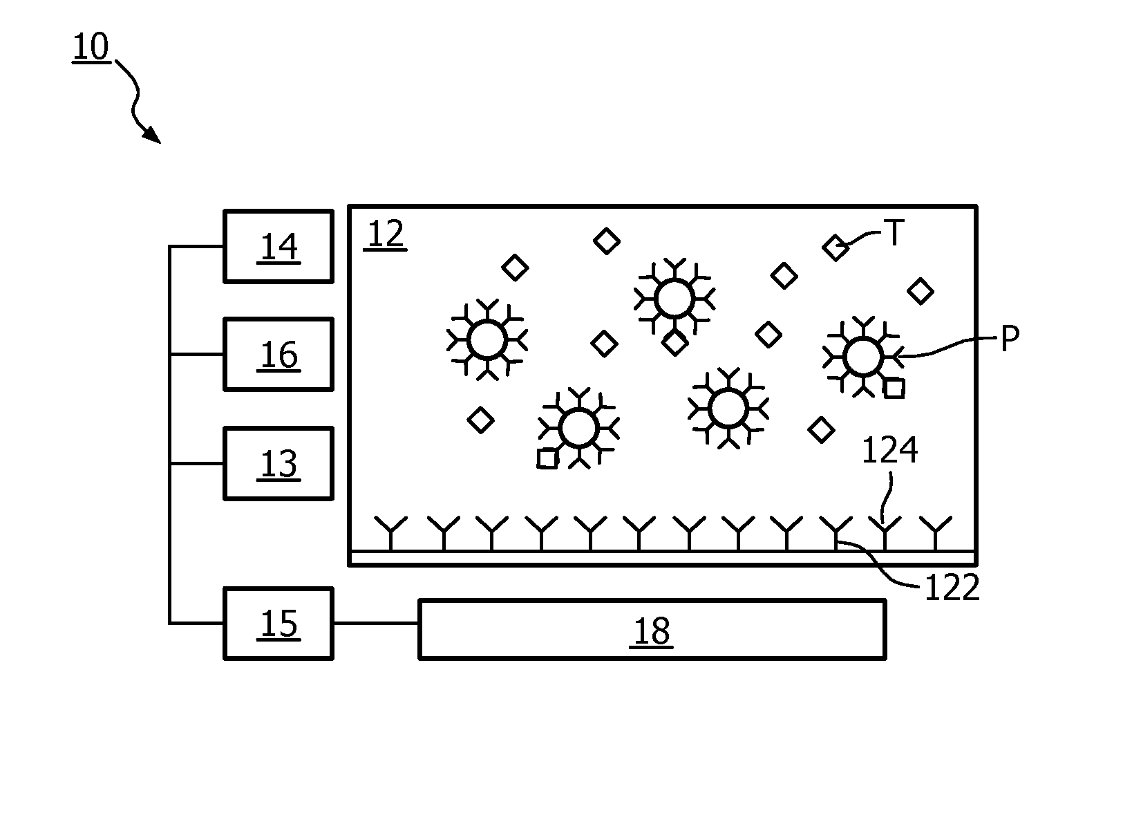
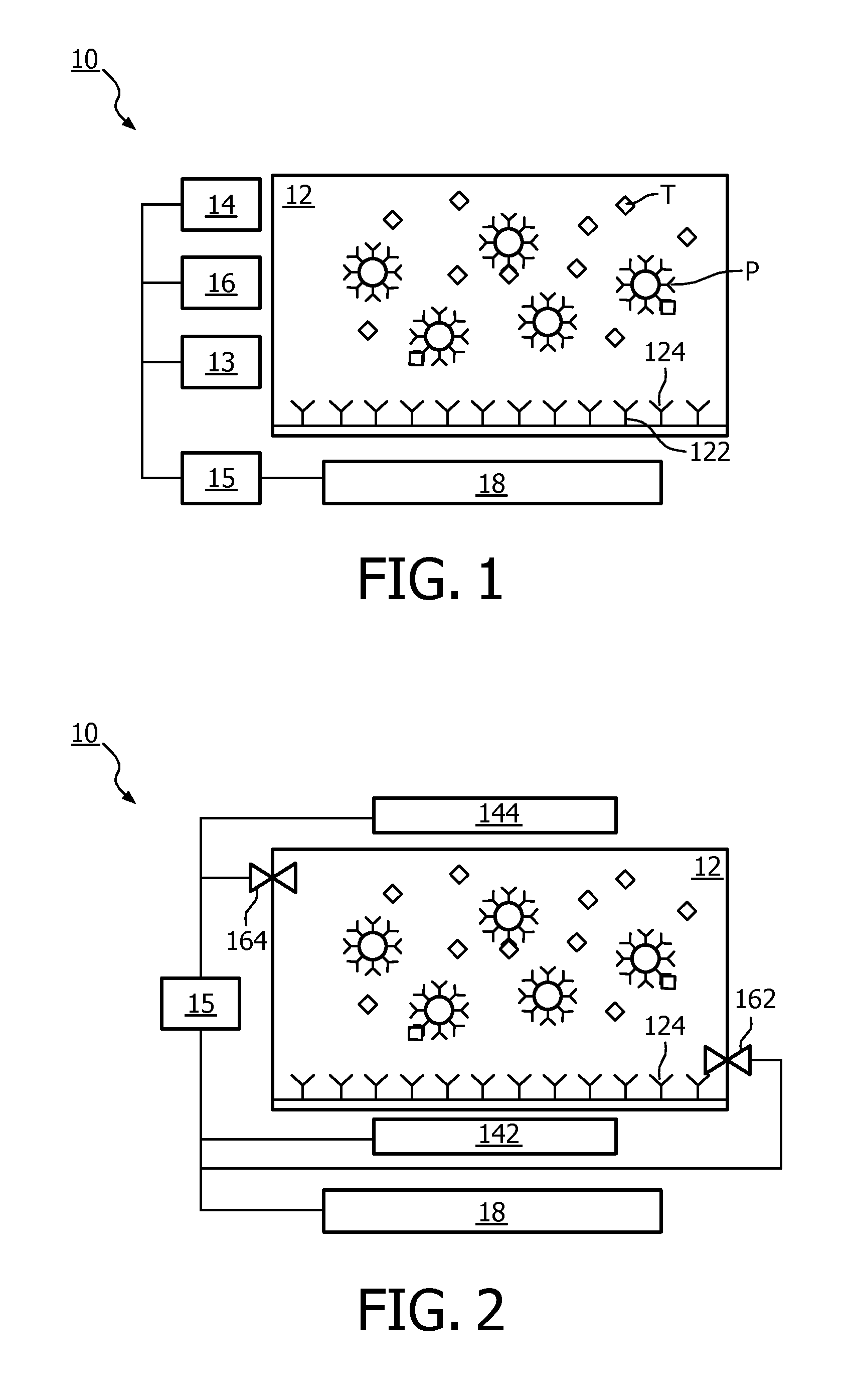
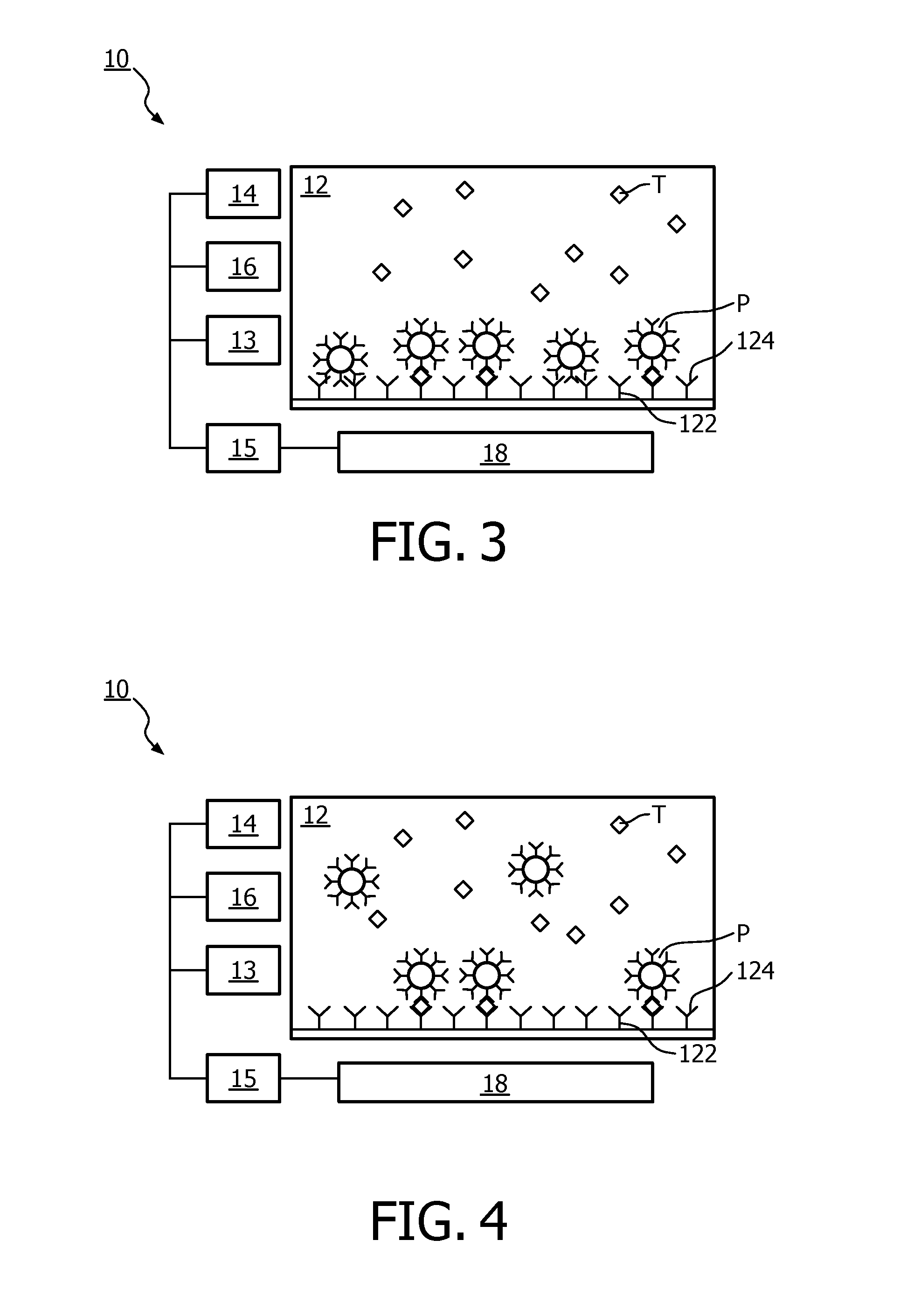
The patent is about a sensor device that can measure the amount of magnetic particles in a sample. The device has a controller that can replace the sample in the device with a new sample until a certain number of cycles is reached. This increases the volume of the sample for detection, improving the sensitivity of the device. The controller can also stop replacing the sample when the measured amount of magnetic particles reaches a certain level, making the detection more flexible.

Problems solved by technology

However, this small sample size could be the limitation / disadvantage for applications such as food safety.
Second, the sensitivity requirement in food safety is very high.
Thus the small sample size may result in either false negative or longer enrichment time.

Method used


Image

  • A sensor device and a method of sampling
  • A sensor device and a method of sampling
  • A sensor device and a method of sampling

Examples


Embodiment Construction

[0056]Reference will now be made to embodiments of the invention, one or more examples of which are illustrated in the figures. The embodiments are provided by way of explanation of the invention, and are not meant as a limitation of the invention. For example, features illustrated or described as part of one embodiment may be used with another embodiment to yield still a further embodiment. It is intended that the invention encompass these and other modifications and variations as come within the scope and spirit of the invention.

[0057]The sensor device of the invention is applicable to a variety of detection scenarios, for example, the sensor device of the invention can be used to detect the concentration of target component in a sample.

[0058]The magnetic separation technology is applied in the sensor device of the invention to achieve the purpose of detection. In one example, the magnetic separation technology can be immunomagnetic separation which uses the mechanism of immune sy...


PUM


Abstract

The invention proposes a sensor device (10) and a method of sampling. The method comprises the steps of: A. adding a sample to a chamber (12) in which magnetic particles (P) are provided, the sample including a target component (T) and the chamber (12) having a detection surface (122); B. exerting a magnetic force on the magnetic particles (P) to attract the magnetic particles (P) to the detection surface (122), wherein bound magnetic particles that capture the target component (T) in the magnetic particles (P) are held at the detection surface (122), and unbound magnetic particles that capture no target component (T) in the magnetic particles (P) are held at the detection surface (122) as well; C. altering the magnetic force exerted on the magnetic particles (P) to release the unbound magnetic particles from the detection surface (122); D. measuring the amount of the bound magnetic particles that are held at the detection surface (122); E. determining whether the amount of the bound magnetic particles that are held at the detection surface (122) is above a predetermined threshold; if no, performing the following steps of: exerting the magnetic force on the magnetic particles to attract the magnetic particles (P) to the detection surface (122); draining at least part of the sample out of the chamber (12) and adding a new sample to the chamber (12); altering the magnetic force exerted on the magnetic particles to release the unbound magnetic particles from the detection surface (122); and going back to perform the steps B to E. By doing so, the target component (T) is preconcentrated by repeating the steps of magnetically binding the target component (T) from the newly added sample and washing the detection surface (122) from unbound magnetic particles.

Description

FIELD OF THE INVENTION[0001]The present invention relates to a sensor device. Moreover, the present invention relates to a method of sampling.BACKGROUND OF THE INVENTION[0002]A biosensor is an analytical device for the detection of an analyte that combines a biological component with a physicochemical detector. The biosensor is now being developed for a variety of applications, such as healthcare, food safety, etc.[0003]One of the current biosensors, for example Magnotech platform, works as follows. When a sample is poured into a chamber, the magnetic beads in the chamber begin to capture the target molecules in the sample via antibodies (called ‘Target capture’). Then, a first magnetic field is applied to attract all of the magnetic beads to a detection surface, coated with antibodies, of the chamber (called ‘Magnetic attraction’), wherein magnetic beads capturing the target molecules (i.e., bound magnetic beads) are bound to the detection surface via antigen-antibody reaction, and...

Claims


Application Information

Patent Timeline
IPC IPC(8): G01N33/543G01N33/02G01N1/28
CPCG01R33/1269G01N27/745G01N33/54333G01N33/54366G01R33/0213G01N35/0098G01N33/02G01N1/40G01N15/0266G01N1/28G01N33/54326G01N33/54386
Inventor KELLY, DECLAN PATRICKXIAO, WEIMIN
Owner KONINKLJIJKE PHILIPS NV
Learn More