
Electricity storage system

a technology of electric storage system and storage system, which is applied in the direction of battery/fuel cell control arrangement, propulsion by batteries/cells, instruments, etc., can solve the problem of difficult charging of batteries to the full soc, and achieve the effect of improving the precision with which the first reference voltage drop amount is specified and improving the accuracy of the first reference voltage drop amoun

Active Publication Date: 2015-08-20
TOYOTA JIDOSHA KK
View PDF6 Cites 32 Cited by
  • Summary
  • Abstract
  • Description
  • Claims
  • Application Information

AI Technical Summary

Benefits of technology

The patent text describes a method for accurately setting the initial voltage level of a battery during charging. The method involves measuring the battery's current at different timings before charging is paused. An average of these current measurements is then calculated to determine the initial voltage level. This average helps to account for any variation in current levels that may occur within the allowed range. Overall, this method improves the accuracy of the initial voltage level of a battery and ensures efficient and reliable charging.

Problems solved by technology

As deterioration of the battery progresses, the internal resistance of the battery increases, and therefore, depending on the voltage drop, it may become difficult to charge the battery to the full SOC.

Method used


Image

  • Electricity storage system
  • Electricity storage system
  • Electricity storage system

Examples


Embodiment Construction

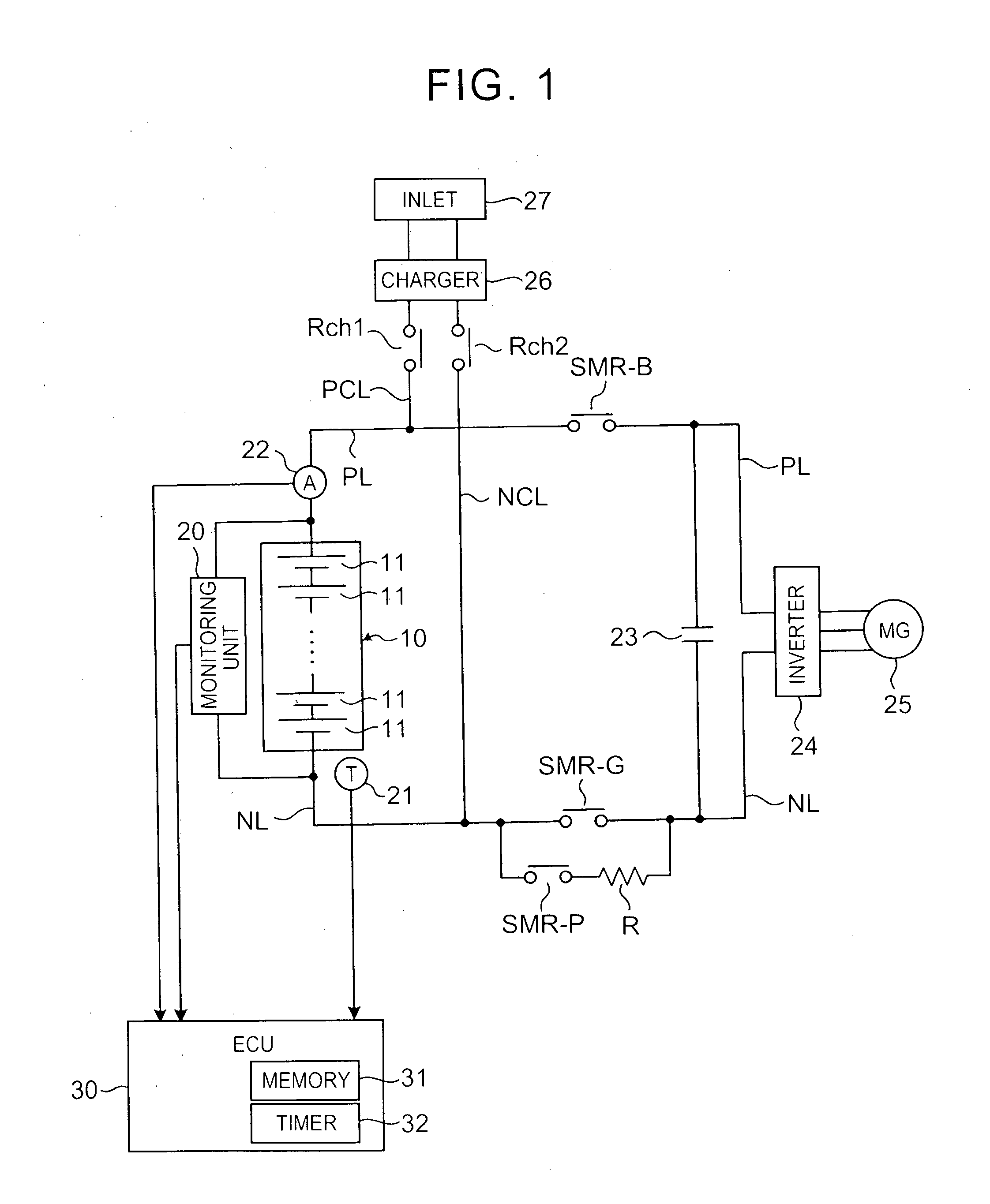
[0031]FIG. 1 is a view showing a configuration of a battery system (which may be considered as an electricity storage system of the invention) according to an embodiment. The battery system shown in FIG. 1 is installed in a vehicle. The vehicle may be a plug-in hybrid vehicle (PHV) or an electric vehicle (EV), for example.

[0032]A PHV includes, as power sources that cause the vehicle to travel, a battery pack to be described below, and another power source such as an engine or a fuel cell. An EV includes only the battery pack to be described below as a power source that causes the vehicle to travel. As will be described below, in both the PHV and the EV, the battery pack can be charged using power from an external power supply.

[0033]Note that in this embodiment, the battery pack is installed in a vehicle, but the invention is not limited thereto, and may be applied to any system capable of charging . a battery pack.

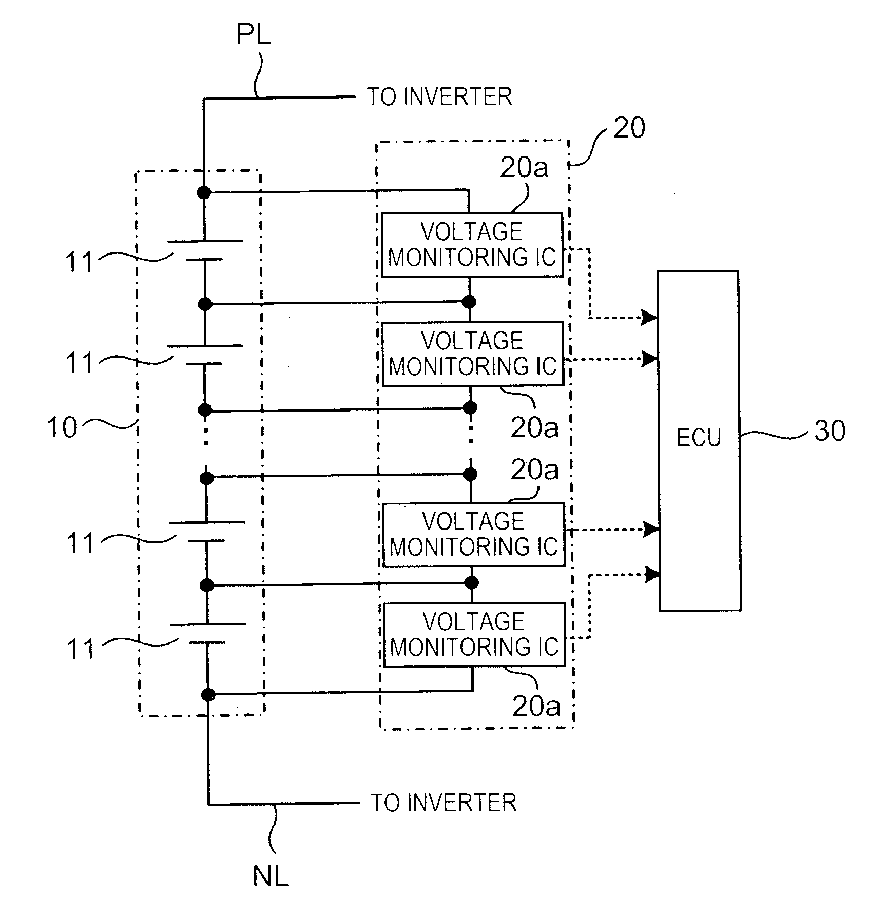
[0034]A battery pack 10 includes a plurality of single cells 11 conne...


PUM


Abstract

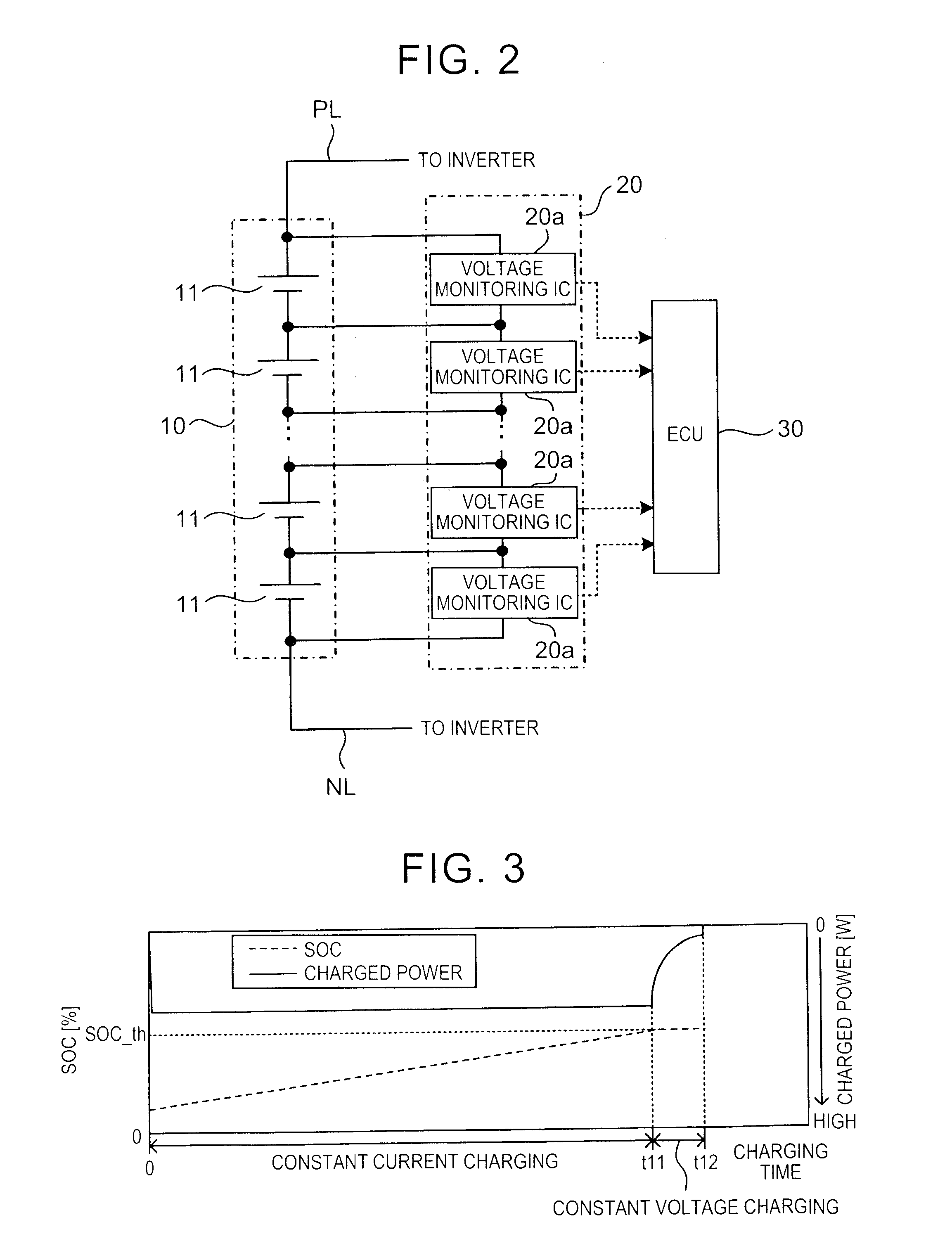
An electricity storage system includes: an electricity storage unit (10, 11) that is subjected to charging and discharging; a voltage sensor (20, 20a) that detects a voltage value of the electricity storage unit; and a controller (30) that terminates the charging of the electricity storage unit when the detected voltage value reaches a charging termination voltage value. The controller calculates a voltage drop, which is associated with interruption of constant current charging, on the basis of the detected voltage value while the constant current charging is performed in the electricity storage unit, and sets the charging termination voltage value in accordance with the amount of voltage drop.

Description

BACKGROUND OF THE INVENTION[0001]1. Field of the Invention[0002]The invention relates to an electricity storage system capable of charging an electricity storage unit.[0003]2. Description of Related Art[0004]Japanese Patent Application Publication No. 08-154307 (JP 08-154307 A) describes charging a battery to a full state of charge (SOC) using an external charger. Here, during the external charging, a shift to constant voltage charging is performed while monitoring a charging current and a terminal voltage of the battery, and when charging has been performed for a predetermined amount of time following a reduction in the charging current, the battery is determined to have reached the full SOC.[0005]While the external charging is underway, a voltage value (a closed circuit voltage (CCV)) of the battery increases above an open circuit voltage (OCV) in accordance with an internal resistance of the battery. When the external charging is completed, the CCV of the battery decreases so as ...

Claims


Application Information

Patent Timeline
IPC IPC(8): H02J7/00G01R31/36
CPCG01R31/362H02J7/007B60L2210/30B60L2240/545B60L2240/547B60L2240/549B60L2240/80B60L2260/42B60L2270/20Y02T10/7072Y02T90/14B60L53/14B60L50/51B60L58/22H02J7/0049B60L58/15H02J2310/48H02J7/007194H02J7/00712Y02T10/70Y02T10/72H02J7/04H02J7/0016H02J7/005G01R31/3835Y02T90/12
Inventor ARIDOME, KOJI
Owner TOYOTA JIDOSHA KK
Learn More