
Method for providing a lamination film with adhesive, method for applying hot melt, application, lamination plant and method for upgrading such a plant

a technology of lamination film and adhesive, applied in the direction of film/foil adhesive, other domestic articles, manufacturing tools, etc., can solve the problems of insufficient vacuum hole capacity, insufficient graining to the component, and insufficient to avoid small to medium air pockets

Active Publication Date: 2015-08-27
PERSICO
View PDF4 Cites 10 Cited by
  • Summary
  • Abstract
  • Description
  • Claims
  • Application Information

AI Technical Summary

Benefits of technology

The patent text describes a method that prevents incomplete or slowed cross-linking of adhesive in areas without air contact. This is achieved by using channels resulting from the gravure coating which are still recognisable in the laminated molded part. Additionally, the patent suggests using an adhesive grid to reduce or avoid air pockets during the lamination process. These improvements lead to a more reliable and efficient component lamination process.

Problems solved by technology

However, this is often not sufficient to avoid small to medium sized air pockets occurring.
This may be caused, for example, by the geometry of the components, but also by the deposition process of the film and the limited capacity of the vacuum holes.
However, the application of this lamination graining to the component is technically complex and costly, especially since a sufficient grain typically requires a depth of 0.2 to 0.3 mm, which leads to a correspondingly higher use of material and also increases the overall weight of the component.
The viscous adhesive can easily clog the vacuum holes or grain channels because of its fluidity.
This prevents the uniform extraction of the air and can thus favour the formation of air pockets.
This results in visible but also invisible defects in the finished laminated molding.
In fact, the expert is aware that these kinds of defects caused by air pockets, often occur when using hot melt adhesives; the demands on grain quality, and the requirements with respect to the quality and depth of the grain as well as the number of holes are higher than in the case of the first-mentioned process, where the adhesive is sprayed on the component.

Method used


Image

  • Method for providing a lamination film with adhesive, method for applying hot melt, application, lamination plant and method for upgrading such a plant
  • Method for providing a lamination film with adhesive, method for applying hot melt, application, lamination plant and method for upgrading such a plant
  • Method for providing a lamination film with adhesive, method for applying hot melt, application, lamination plant and method for upgrading such a plant

Examples


Embodiment Construction

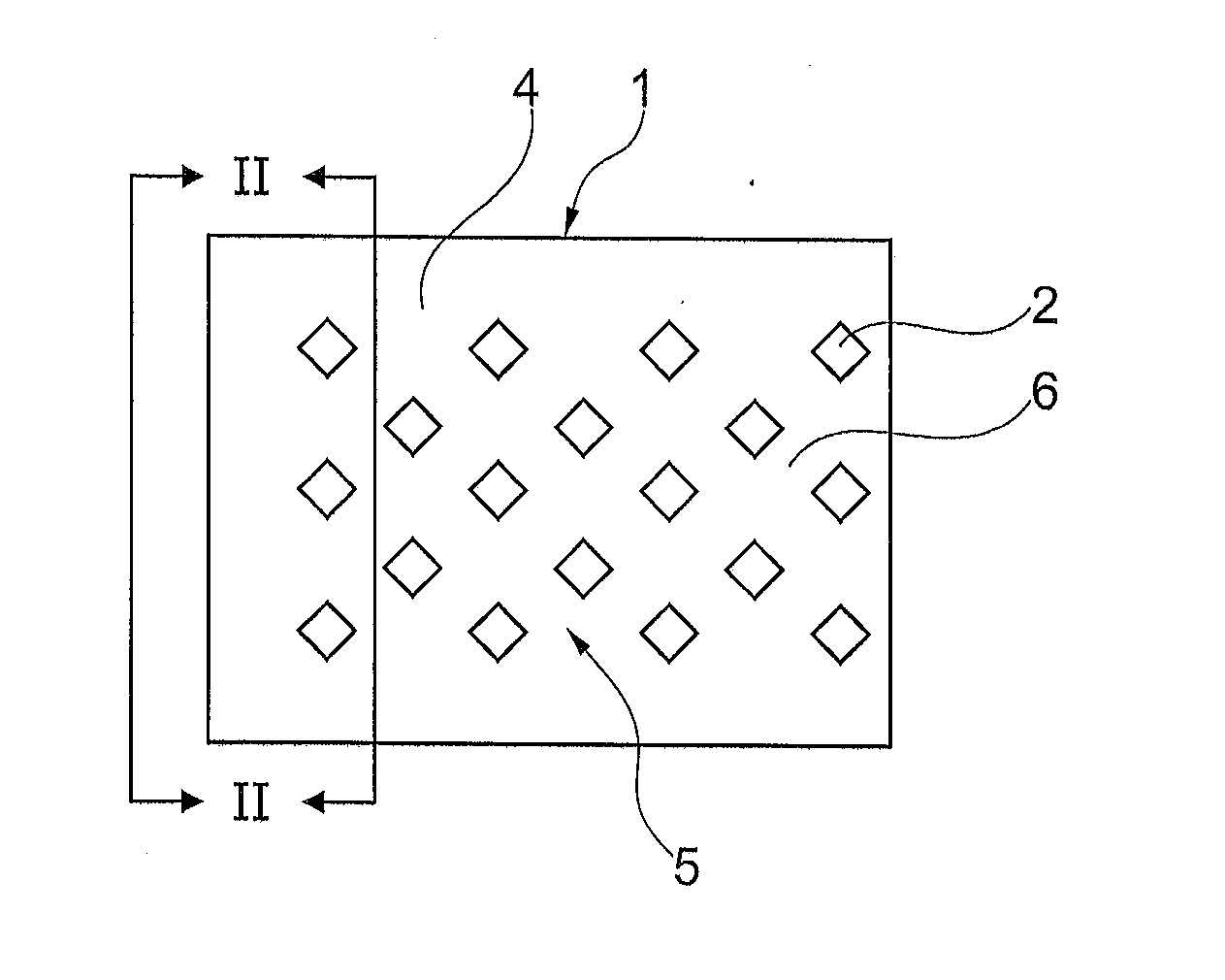
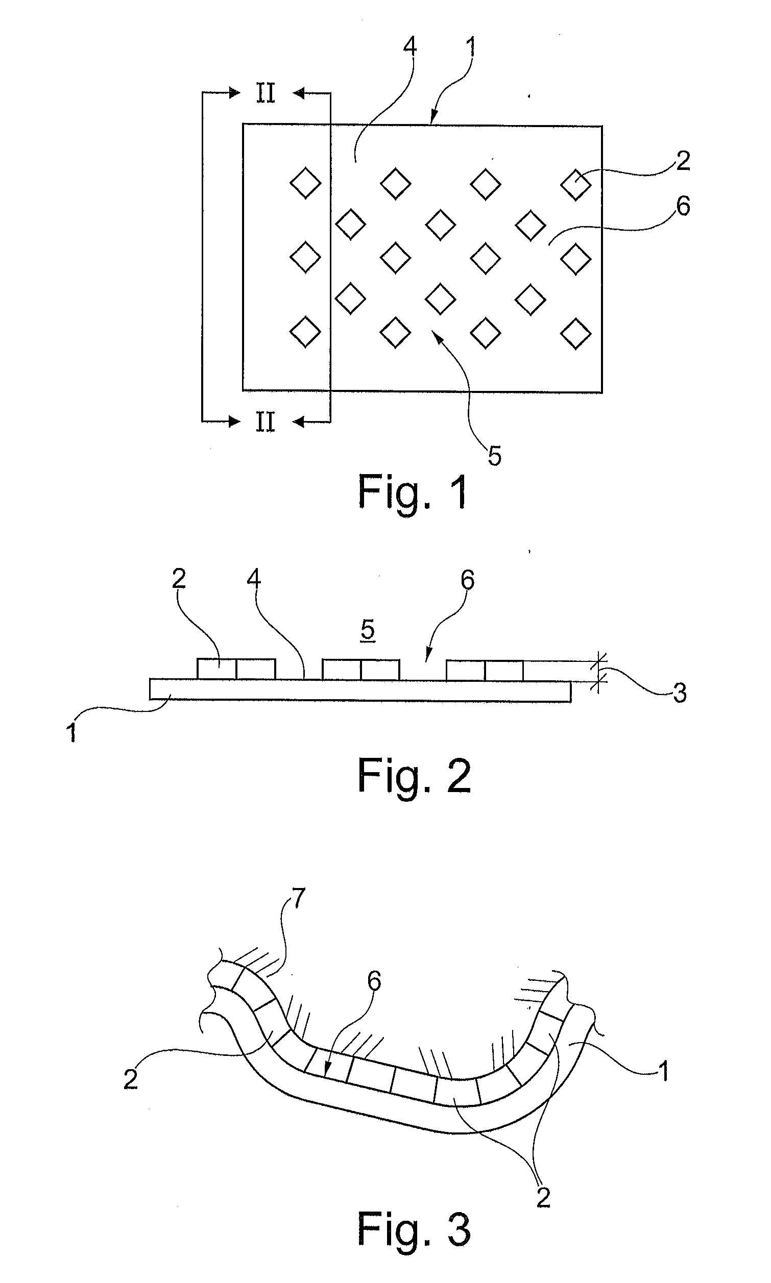
[0179]The laminate film 1 in FIG. 1 is made up of a substantially two-dimensional art material film, which is meant to dress an interior panel part on the body of a motor vehicle and to be laminated on a support part with the B-side in FIG. 1 visible.

[0180]In preparing the compound, a hot melt is applied to laminate film 1, and in a variety of rhombuses 2 (labeled). Each rhombus 2 has a height of 3, with which it rises above a surface 4 on the B-side 5 of the laminate film 1.

[0181]In between the rhombus 2, a system of ducts is generated that are fully linked with each other.

[0182]Laminate film 1 is now laminated in a mold on support part 7 (see FIG. 3), thus keeping height 3 of rhombuses 2 upright from the hot melt of the open linked feature of duct system 6. The air in the tool can be removed laterally. It flows through the free cross-section of the duct system 6. Here, laminate film 1 moves even closer step by step to support part 7 until a direct positive fit lock finally occurs ...


PUM

PropertyMeasurementUnit
depthaaaaaaaaaa
temperatureaaaaaaaaaa
thicknessaaaaaaaaaa

Abstract

A method for providing a laminate film with adhesive as a step in the preparatory process for manufacturing a laminate mold part using a support part, a method for applying a hot melt to a laminate film, a method for manufacturing a laminate mold part, using a method, a system for laminating a support part as well as a method for such a system produces especially high quality lamination and even if the support part, where the laminate film should be laminated, is not porous by applying the adhesive to the support part for bonding the macroscopically structured laminate film, so that there is a duct system. The air can flow through the duct system between the laminate film and the support part during the lamination process.

Description

CROSS REFERENCE TO RELATED APPLICATIONS[0001]Applicant claims priority under 35 U.S.C. §119 of German Application No. 10 2014 002 568.6 filed Feb. 26, 2014, the disclosure of which is incorporated by reference.BACKGROUND OF THE INVENTION[0002]1. Field of the Invention[0003]The present invention relates to a method for providing a lamination film with adhesive, a method for applying hot melt to a lamination film, the application for such a method, a plant for laminating a carrier member with a lamination film, as well as a method for upgrading a plant.[0004]In particular, the invention relates to a method for laminating components with film, whereby an adhesive is so applied in grid pattern to the surface of the lamination film and / or the component, and that, after assembling the film and the component, the adhesive is arranged between the film and the component, and a channel system formed between the areas of applied adhesive to enable the uniform removal of the air lying between t...

Claims


Application Information

Patent Timeline
Patent Type & Authority Applications(United States)
IPC IPC(8): B32B37/12B32B37/10C09J7/20
CPCB32B37/1292B32B37/1009B32B2605/003B32B2398/20B32B2037/1215B32B37/1207B32B37/003B29C63/0047B32B37/0053B32B38/06B32B2307/7242B32B2307/734B32B2309/02B32B2309/68C09J7/20Y10T156/1744Y10T29/49716C09J2301/204B60R13/02B60R13/0256B32B7/14B60R13/0262
Inventor DANDL, ANDREAS
Owner PERSICO
Learn More