

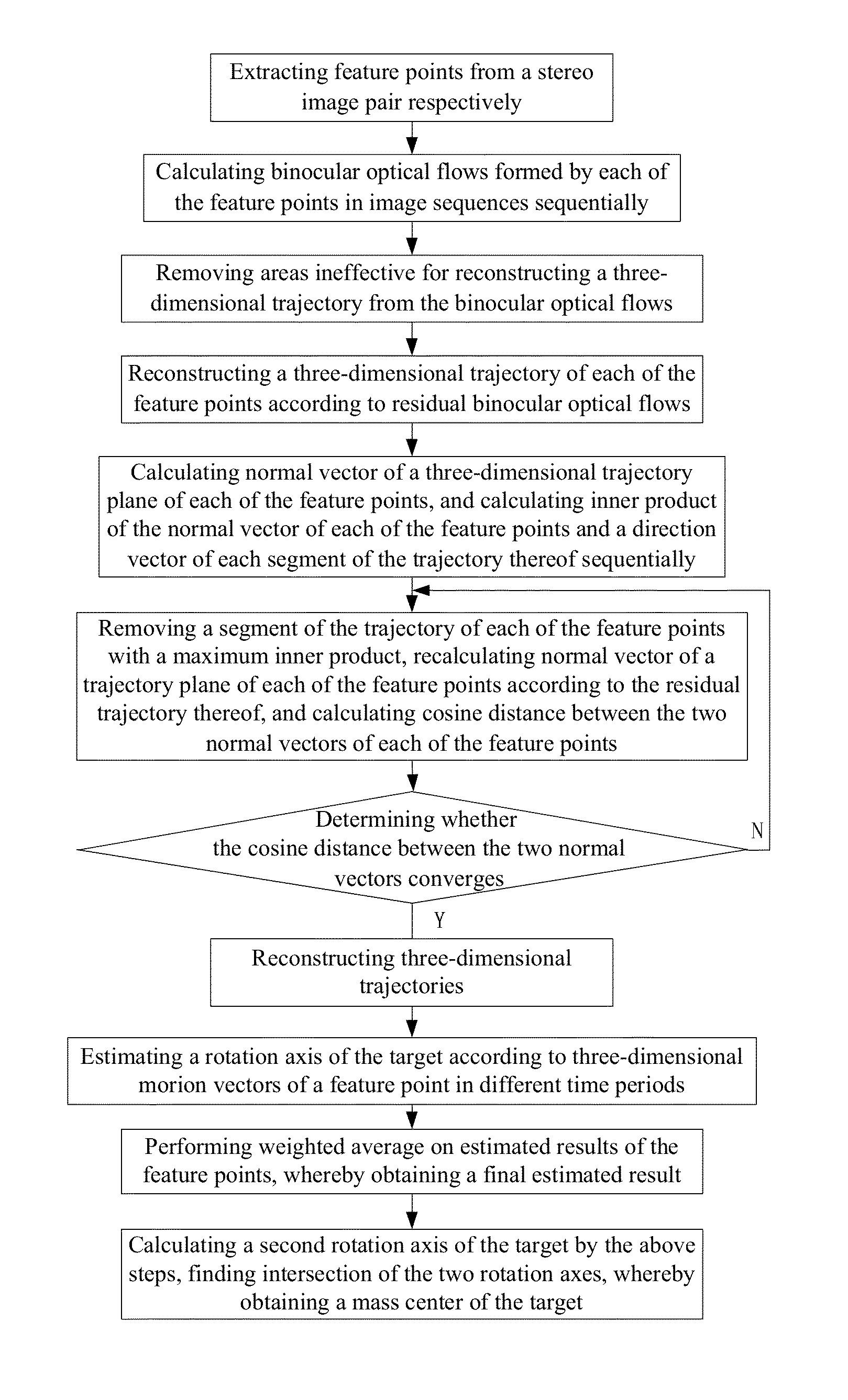
Method for estimating rotation axis and mass center of spatial target based on binocular optical flows
a technology of binocular optical flow and spatial target, which is applied in the field of method for estimating the rotation axis and mass center of the spatial target based on binocular optical flow, can solve the problems of limited reconstruction methods in prior art, affecting the accuracy of spatial target trajectory reconstruction, and affecting the adaptability of autonomous navigation, etc., so as to achieve accurate reconstruction of spatial target trajectory and remove areas
- Summary
- Abstract
- Description
- Claims
- Application Information
AI Technical Summary
Benefits of technology
Problems solved by technology
Method used
Image

Examples
Embodiment Construction
[0045]For clear understanding of the objectives, features and advantages of the invention, detailed description of the invention will be given below in conjunction with accompanying drawings and specific embodiments. It should be noted that the embodiments are only meant to explain the invention, and not to limit the scope of the invention.
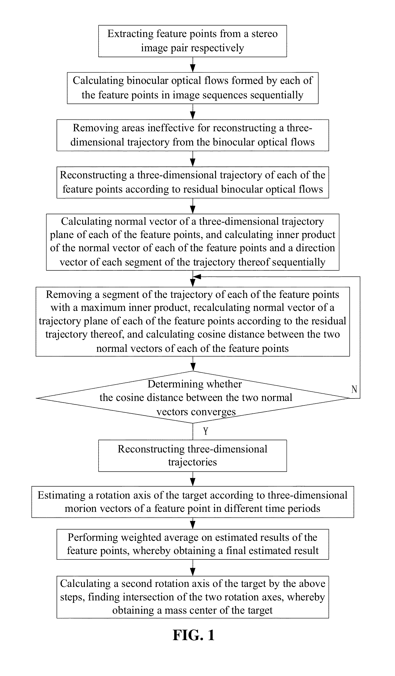
[0046]Related concepts and terminologies are illustrated first for better understanding of the present invention, comprising three coordinate systems in machine vision: image coordinate system (U,V), camera coordinate system and spatial coordinate system, where image data captured by machine vision are illustrated by an image coordinate system, namely row and column locations of pixels of an image, objective locations and sizes of measured objects and interrelations therebetween are illustrated by a spatial coordinate system, and the two coordinate systems are transformed by a camera coordinate system.
[0047]1. Image Coordinate System
[0048]Digital ...
PUM
 Abstract
Description
Claims
Application Information