Surveillance system, surveillance camera and method for security surveillance

a security surveillance and surveillance system technology, applied in the field of surveillance systems, can solve problems such as damage or loss in single-floor areas, and exist security vulnerability in the security surveillance system, and achieve the effect of overcoming the security vulnerability in the surveillance system

Inactive Publication Date: 2015-08-27
TRANSCEND INFORMATION
View PDF11 Cites 19 Cited by
  • Summary
  • Abstract
  • Description
  • Claims
  • Application Information

AI Technical Summary

Benefits of technology

[0006]In view of the above, an object of the present disclosure is to provide a surveillance system, a surveillance camera, and a method for security surveillance for solving the mentioned disadvantages existed in prior art, that is, once one of surveillance cameras is disabled, at least one of the others will support the disabled surveillance camera for outwardly transmitting the real-time videos of the viewing zone which the disabled surveillance camera originally covers, so that the security vulnerability existed in the surveillance system can be overcome.

Problems solved by technology

However, since the surveillance cameras respectively provide different viewing zones of the single-floor area, once one of the surveillance cameras is disabled, the disabled surveillance camera fails to provide the real-time videos of the viewing zone which the disabled surveillance camera originally covers via the monitor screen, and neither do the other surveillance cameras, so that a security vulnerability is existed in the security surveillance system.
Even if the user arrives the single-floor area from the control center quickly, damages or loses in the single-floor area might has been happened already before the user arrives the disabled surveillance camera from the control center.

Method used


Image

  • Surveillance system, surveillance camera and method for security surveillance
  • Surveillance system, surveillance camera and method for security surveillance
  • Surveillance system, surveillance camera and method for security surveillance

Examples


first embodiment

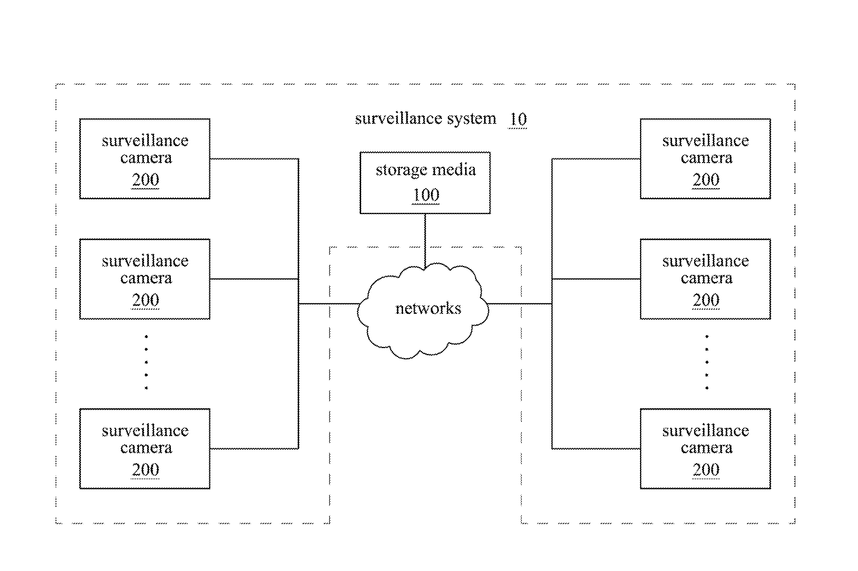
[0024]Reference is now made to FIG. 1 in which FIG. 1 is a block diagram illustrating a surveillance system 10 according to a first embodiment of the disclosure. As shown in FIG. 1, in the embodiment, the surveillance system 10 at least comprises a plurality of surveillance cameras 200. These surveillance cameras 200 are respectively deployed at different parts of a single-floor area, thus, these surveillance cameras 200 respectively have a viewing zone different to each other, that is, each surveillance camera 200 covers a different viewing zone of the single-floor area from the other surveillance cameras 200. Thus, these surveillance cameras 200 respectively transmit and record the real-time videos of the corresponding viewing zone of the single-floor area outwardly to a storage media 100 (e.g., digital video recorder, DVR). The surveillance cameras 200 are electrically connected with each other via networks, in particular, in this embodiment, the surveillance cameras 200 are elec...

second embodiment

[0037]FIG. 3A and FIG. 3B are practice schematic views illustrating a surveillance system 11 exercising in a single-floor area 400 according to a second embodiment of the disclosure. For example, refer to FIG. 3A, the surveillance system 11 includes surveillance cameras #1 to #4, for monitoring a single-floor area 400 having zones A to C in which the surveillance camera #1 is located at the zone A and provides a viewing zone facing towards a right side 400R of the single-floor area 400, the surveillance camera #2 is located at the zone B and provides a viewing zone facing towards a bottom side 400B of the single-floor area 400, the surveillance camera #3 is located at the zone C and provides a viewing zone facing towards a left side 400L of the single-floor area 400, and the surveillance camera #4 is also located at the zone C and provides a viewing zone facing towards the bottom side 400B of the single-floor area 400.

[0038]The surveillance system 11 further optionally includes a co...

third embodiment

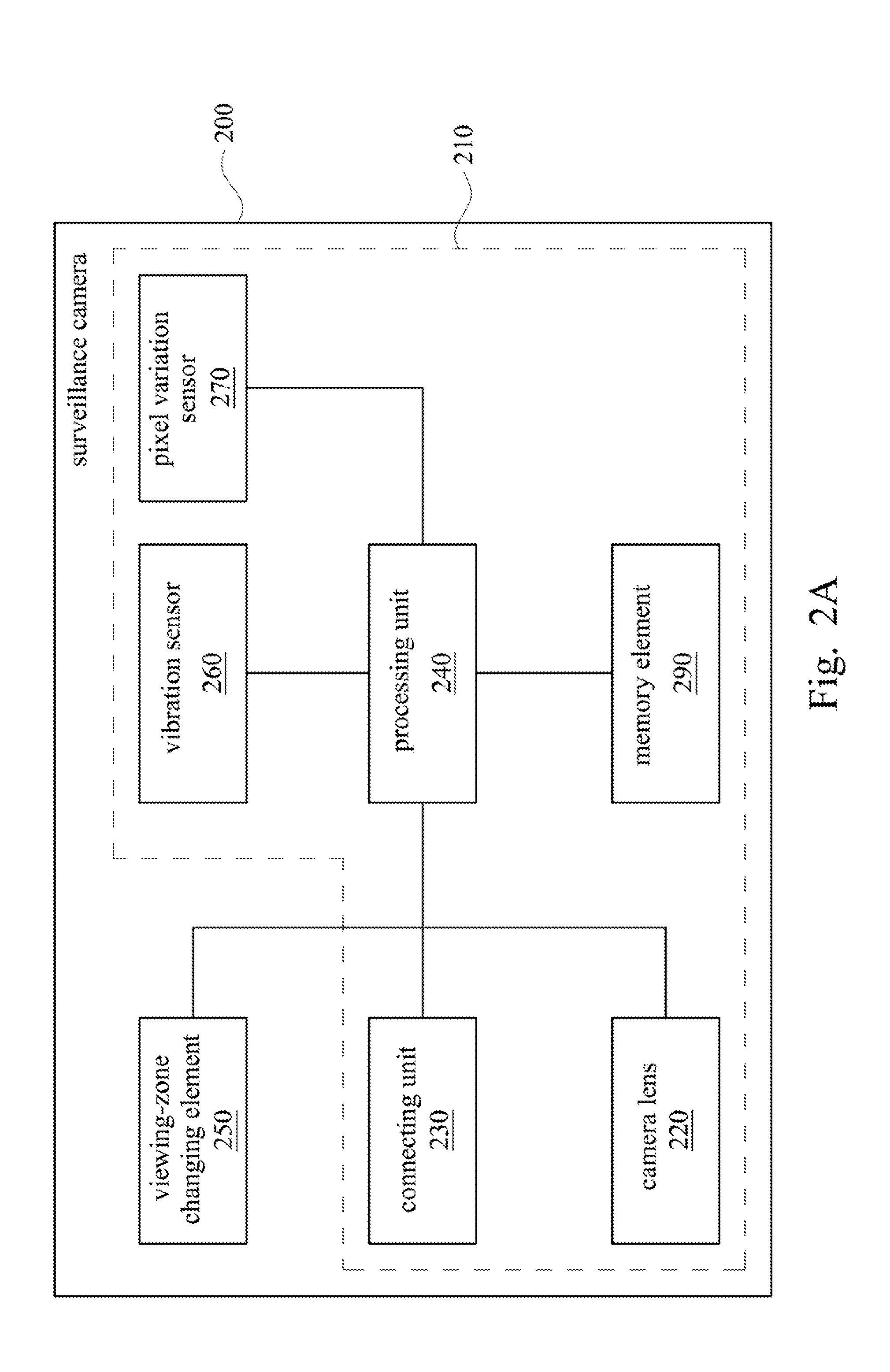
[0045]Reference is now made to FIG. 6 in which FIG. 6 is a block diagram illustrating a surveillance camera 400 according to a third embodiment of the disclosure. The surveillance camera 400 is substantially the same as the surveillance camera 200 of the first embodiment except that the surveillance camera 400 further includes a positioning transceiver 410, e.g., a global position system (GPS) transceiver, and a calculation element 420. The positioning transceiver 410 electrically connects to the processing unit 240. The positioning transceiver 410 is configured to output a location data, such as GPS data, of the surveillance camera 400 for notifying the GPS coordinate to the other surveillance cameras 400. The calculation element 420 electrically connects to the processing unit 240. When one of the surveillance cameras 400 obtains location data of the disabled surveillance camera, the calculation element 420 will calculate to generate a suggested rotation angle by using the locatio...


PUM


Abstract

A surveillance system, a surveillance camera, and a method for security surveillance are provided. The surveillance system includes at least one first surveillance camera and a second surveillance camera electrically connected to the first surveillance camera via networks. When the first surveillance camera detects and determines that the second surveillance camera is disabled, the first surveillance camera changes a first viewing zone to overlap a second viewing zone of the second surveillance camera.

Description

BACKGROUND[0001]1. Field of Disclosure[0002]The present disclosure relates to surveillance system. More particularly, the present disclosure relates to surveillance system, a surveillance camera, and a method for security surveillance.[0003]2. Description of Related Art[0004]Recently, surveillance cameras in a security surveillance system are respectively deployed at different parts of a single-floor area, and the surveillance cameras are respectively used to monitor the different parts of the single-floor area for security surveillance. Since the surveillance cameras are connected to a control center via networks, the surveillance cameras respectively capture real-time videos and respectively output to the control center via the networks. Thus, a user at the control center is able to view the real-time videos captured by the surveillance cameras via a monitor screen remotely, so the user can take actions according to the real-time videos shown on the monitor screen, especially when...

Claims


Application Information

Patent Timeline
Patent Type & Authority Applications(United States)
IPC IPC(8): H04N7/18H04N5/232
CPCH04N5/23296H04N7/181G08B13/19641G08B13/19645G08B29/18H04N23/661H04N23/69H04N23/695H04N23/90
Inventor LIAO, MAO-YU
Owner TRANSCEND INFORMATION
Why Eureka
Try Eureka