
Integrated system security method

a security method and integrated system technology, applied in the direction of unauthorized memory use protection, anti-theft devices, instruments, etc., can solve the problems of high price of systems, easy to be easily unauthorized use and theft, and types of electronic equipment that have no means to disable equipment, etc., to achieve the effect of simple serial interfa

Inactive Publication Date: 2006-07-11
INT BUSINESS MASCH CORP
View PDF22 Cites 17 Cited by
  • Summary
  • Abstract
  • Description
  • Claims
  • Application Information

AI Technical Summary

Benefits of technology

This solution renders electronic devices useless without the correct password, preventing theft and misuse by ensuring that sub-components are securely protected and cannot be replicated or circumvented, thereby nullifying the purpose of theft.

Problems solved by technology

The accelerated pace of integration and rapid miniaturization of electronic equipment, such as personal computers (PC), laptop personal computers, digital cameras, and video recording equipment, and similar equipment makes these expensive systems highly portable and easily susceptible to unauthorized use and theft.
These types of electronic equipment have no means to disable the equipment and render them useless in order to prevent unauthorized use or theft.
The problems resulting from theft or unauthorized of such equipment often leads to the financial loss and inconvenience of procuring a new system, or the owner's proprietary information and confidential data stored within the system is exposed to potentially undesired uses.
The result is a fixed permanent security code arrangement for that device only and no option exists to permit end users and owners to create a personalized identification code.
In order to secure the radio, a user must remove the mating piece in order to cripple the device and render it useless.
This can be very inconvenient.
This method does not lend itself to protecting multiple sub-components within the same system and is not easy to use.
Whenever software techniques are employed, circumvention is a possibility and detection of circumvention is difficult.
In software based, password only protection schemes, the software itself is prone to alteration or modification which may permit specific or general unauthorized use or access to a system.

Method used


Image

  • Integrated system security method
  • Integrated system security method
  • Integrated system security method

Examples


Embodiment Construction

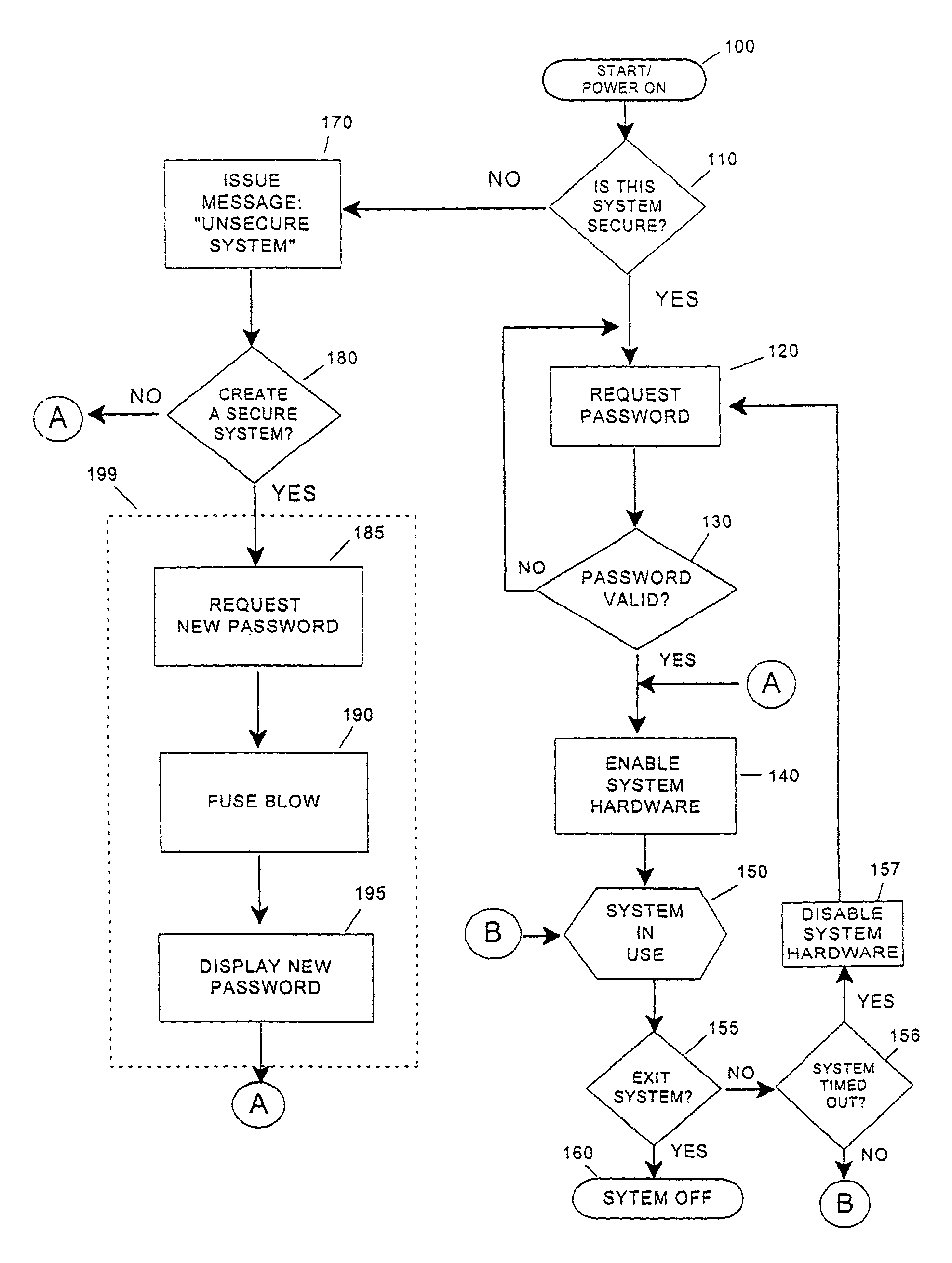
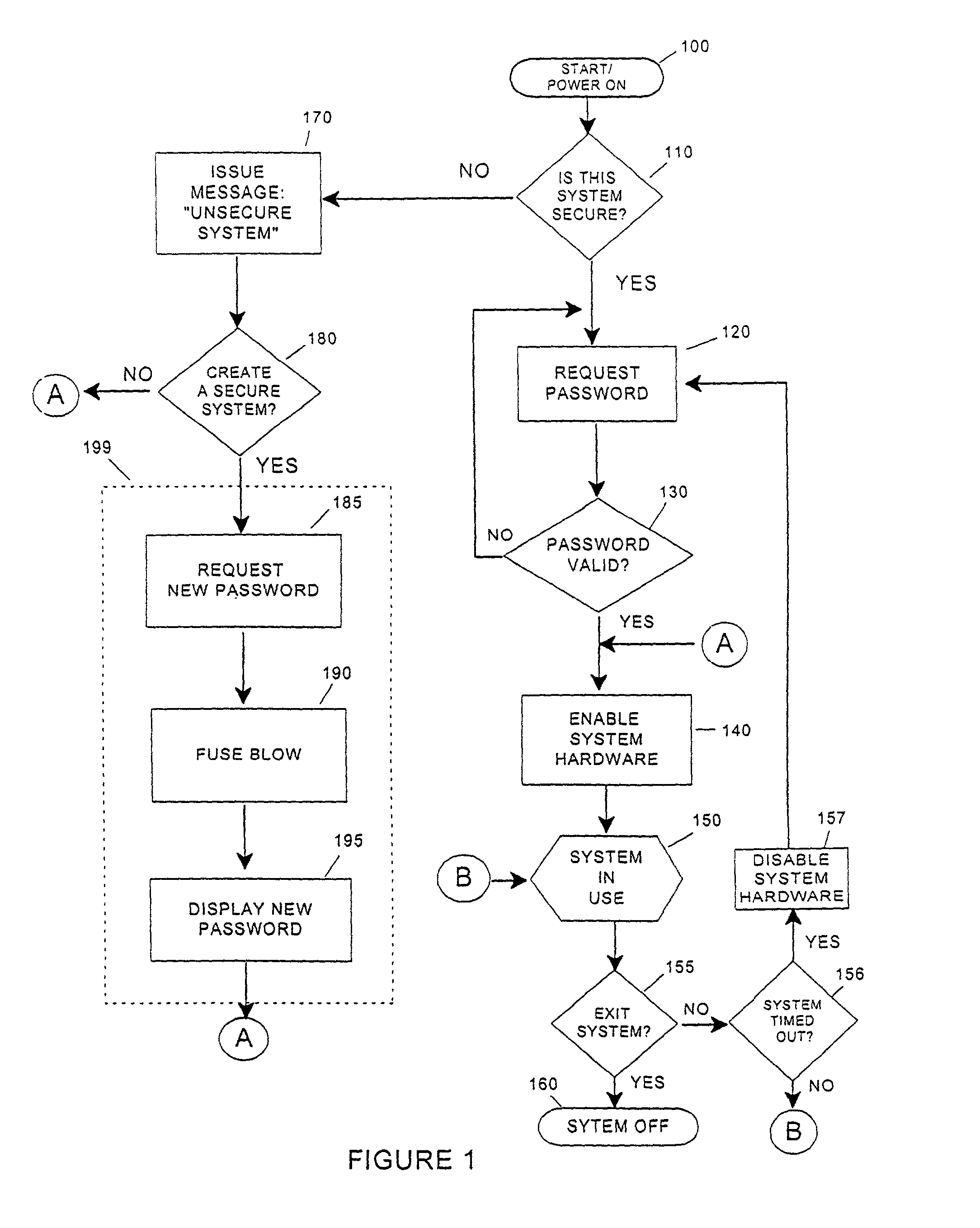
[0026]Referring now to the drawings, and more particularly to FIG. 1, there is shown an overall flow of the security process and gives a general orientation of the nature of the invention's use. Since this invention provides a means to secure electronic devices or devices containing electronic controls, FIG. 1 illustrates the main elements of the process of securing a new device or system the first time, and it also shows the steps to gain access to a device that has previously been secured. The process begins at 100 by powering on the device or system. The login utility software checks in decision block 110 whether the device or system is a secured or unsecured system. The login procedure typically is under a software utility control, but may be implemented entirely in hardware for devices with no significant software elements. An unsecured system is one that has never executed a securing procedure 199 for the device or system and is completely open for general access or use since ...


PUM


Abstract

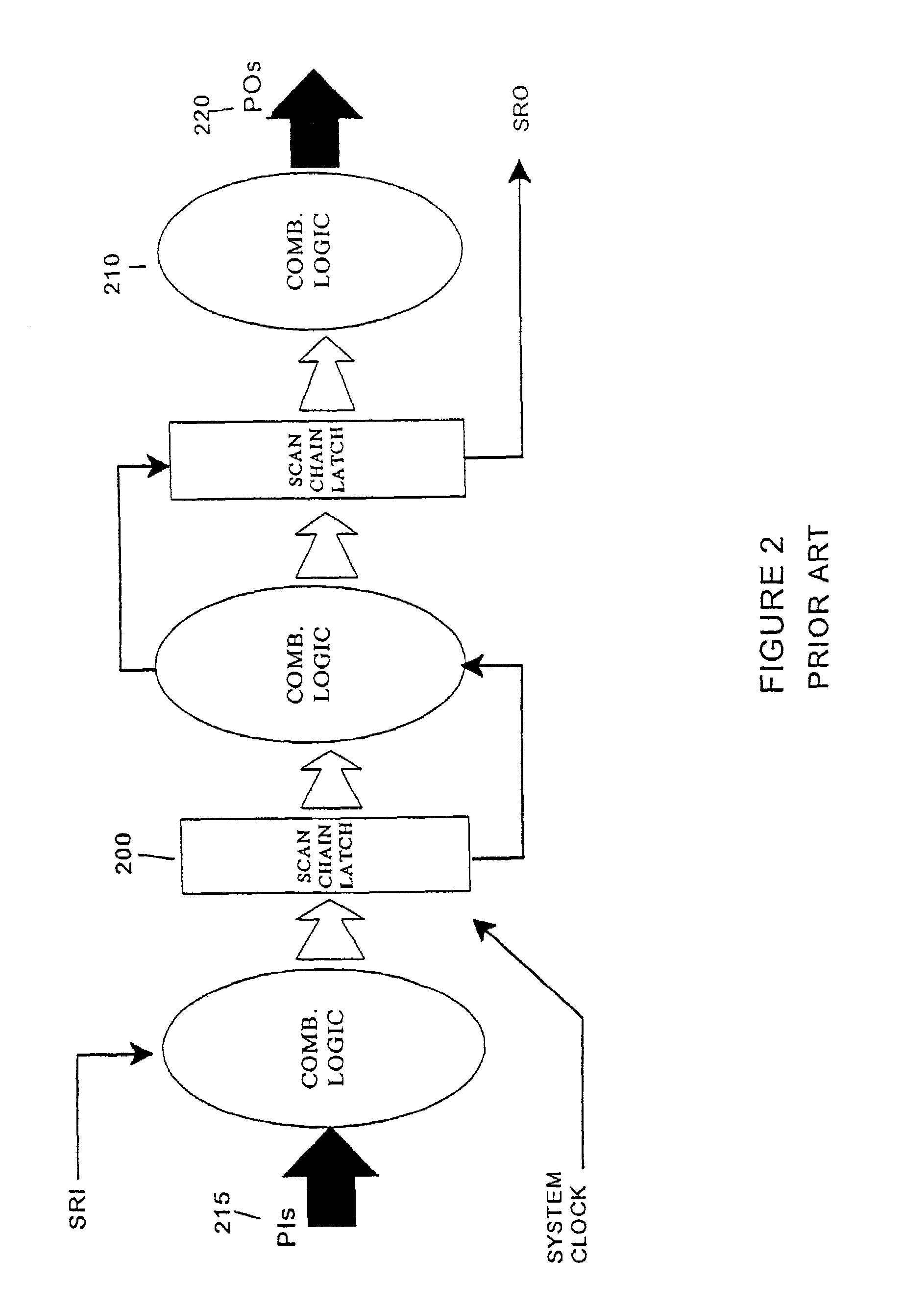
Logic scan based design and electronic fuse (e-fuse) technology are combined to create a circuit macro function that is integrated in a non-critical area of a processor chip or related circuit to provide a new means of securing electronic systems and devices such as computers, appliances, consumer electronics, automobiles, etc. from theft or unauthorized use. Level sensitive scan design (LSSD) techniques are used in conjunction with e-fuses to inhibit or enable system components and sub-components based upon a pre-initialized configuration which must be enabled by a user via password entry.

Description

BACKGROUND OF THE INVENTION[0001]1. Field of the Invention[0002]The present invention generally relates to security methods of electronic devices and, more particularly, to a method of providing a means to prevent unauthorized use or theft of electronic equipment.[0003]2. Background Description[0004]The accelerated pace of integration and rapid miniaturization of electronic equipment, such as personal computers (PC), laptop personal computers, digital cameras, and video recording equipment, and similar equipment makes these expensive systems highly portable and easily susceptible to unauthorized use and theft. This problem can be further extended to larger home appliances, motor vehicles, electronic locks, and other consumer products.[0005]These types of electronic equipment have no means to disable the equipment and render them useless in order to prevent unauthorized use or theft. The problems resulting from theft or unauthorized of such equipment often leads to the financial loss...

Claims


Application Information

Patent Timeline
Patent Type & Authority Patents(United States)
IPC IPC(8): H04K1/00H04L9/00B60R25/00G06F21/00G07C9/00
CPCG06F21/31G07C9/00142G06F21/88G07C9/33
Inventor KELLEY, EDWARD E.MOTIKA, FRANCOMOTIKA, PAUL V.MOTIKA, ERIC M.
Owner INT BUSINESS MASCH CORP
Learn More