Pre-heater latch and seal mechanism for wave solder machine and related method

a technology of latch and seal mechanism, which is applied in the direction of soldering apparatus, lighting and heating apparatus, furnaces, etc., can solve the problems of not being easily replaced, pre-heater assemblies lack the ability to hinge down and decompress seals, etc., and achieve the effect of preserving the substantially oxygen-free environment within the tunnel

Active Publication Date: 2015-08-27
ILLINOIS TOOL WORKS INC
View PDF0 Cites 6 Cited by
  • Summary
  • Abstract
  • Description
  • Claims
  • Application Information

AI Technical Summary

Benefits of technology

[0010]Another aspect of the present disclosure is directed to a method of sealing a tunnel from a pre-heater within a wave soldering machine of the type comprising a pre-heating station including at least one pre-heater and configured to heat the electronic substrate, a wave soldering station configured to attach electronic components to the electronic substrate with solder, and a conveyor configured to transport substrates through a tunnel passing through the pre-heating station and the wave soldering station, with the tunnel having a substantially oxygen-free environment. In one embodiment, the method comprises: positioning a at least one seal between a heater assembly of the pre-heater and a support frame assembly; and securing the at least one seal to the support frame assembly with a retainer, with the at least one seal providing a gas-tight seal when the heater assembly is in an operational position to prevent atmosphere from entering the tunnel thereby preserving the substantially oxygen-free environment within the tunnel.

Problems solved by technology

Prior pre-heater assemblies lack the ability to hinge down to decompress a seal and remove contact between the pre-heater and the seal.
Prior seals were typically attached by adhesives or mechanical fasteners, and thus are not easily replaced.

Method used


Image

  • Pre-heater latch and seal mechanism for wave solder machine and related method
  • Pre-heater latch and seal mechanism for wave solder machine and related method
  • Pre-heater latch and seal mechanism for wave solder machine and related method

Examples


Embodiment Construction

[0025]For the purposes of illustration only, and not to limit the generality, the present disclosure will now be described in detail with reference to the accompanying figures. This disclosure is not limited in its application to the details of construction and the arrangement of components set forth in the following description or illustrated in the drawings. The principles set forth in this disclosure are capable of other embodiments and of being practiced or carried out in various ways. Also the phraseology and terminology used herein is for the purpose of description and should not be regarded as limiting. The use of “including,”“comprising,”“having,”“containing,”“involving,” and variations thereof herein, is meant to encompass the items listed thereafter and equivalents thereof as well as additional items.

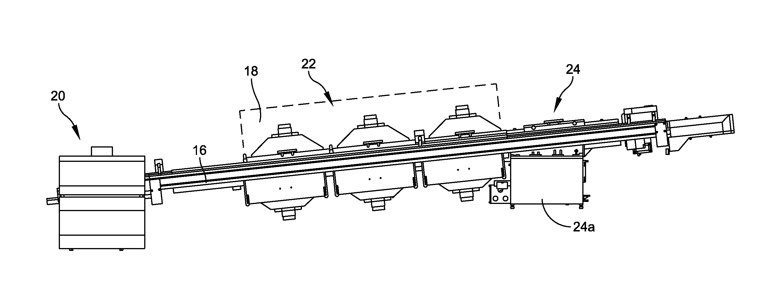
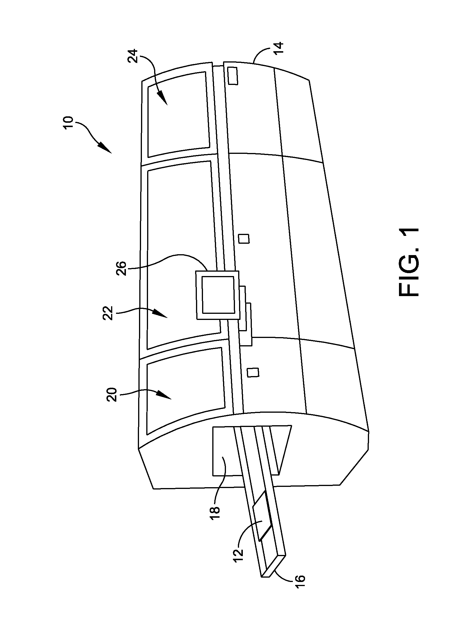
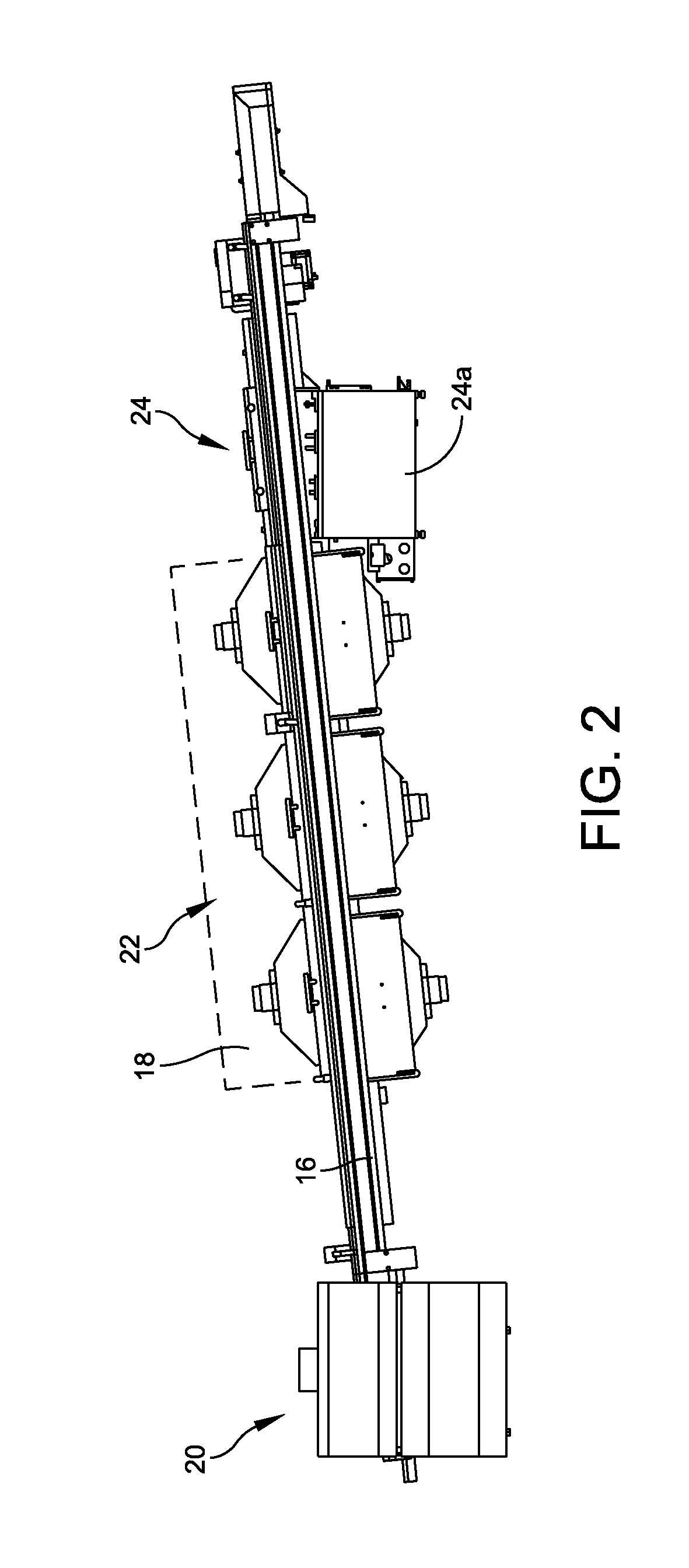
[0026]Wave solder machines are typically designed to incorporate a series of pre-heaters which serve the purpose of heating a printed circuit board (“PCB”) prior to contact wi...


PUM

PropertyMeasurementUnit
shapeaaaaaaaaaa
movementaaaaaaaaaa
temperatureaaaaaaaaaa

Abstract

A wave solder machine includes a pre-heating station, a wave soldering station, and a conveyor to transport substrates through a tunnel passing through the pre-heating station and the wave soldering station. The tunnel has a substantially oxygen-free environment. The pre-heating station includes a pre-heater including a support frame assembly, and a heater assembly supported by the support frame assembly. The heater assembly is slidably coupled to the support frame assembly between an operational position and a non-operational position. The pre-heater further includes a seal disposed between the heater assembly and the support frame assembly. The seal provides a gas-tight seal when the heater assembly is in the operational position to prevent atmosphere from entering the tunnel thereby preserving the substantially oxygen-free environment within the tunnel.

Description

BACKGROUND OF THE INVENTION[0001]1. Field of the Disclosure[0002]This application relates generally to the surface mount of electronic components onto a printed circuit board by employing a wave soldering process, and more particularly to a latch and seal mechanism that is configured to ensure an oxygen-free environment during the wave soldering process.[0003]2. Discussion of Related Art[0004]In the fabrication of printed circuit boards, electronic components can be mounted to a printed circuit board by a process known as “wave soldering.” In a typical wave solder machine, a printed circuit board is moved by a conveyor on an inclined path past a fluxing station, a pre-heating station, and finally a wave soldering station. At the wave soldering station, a wave of solder is caused to well upwardly (by means of a pump) through a wave solder nozzle and contact portions of the printed circuit board to be soldered. As used herein, the term “circuit board” or “printed circuit board,” as us...

Claims


Application Information

Patent Timeline
Patent Type & Authority Applications(United States)
IPC IPC(8): H05K3/34B23K3/08B23K3/06
CPCH05K3/341B23K3/0653B23K3/082B23K1/085H05K2203/044H05K3/34H05K3/3468H05K2203/111H05K2203/04B23K1/0016B23K1/008F27B17/0025Y10T29/49826B23K3/08F27B9/029H01T23/00B23K3/047
Inventor DAUTENHAHN, JONATHAN M.
Owner ILLINOIS TOOL WORKS INC
Why Eureka
Try Eureka