
Method and device for collecting a light underwater fluid such as fresh water or hydrocarbons

a technology of fresh water or hydrocarbons, applied in the field of methods and devices for collecting light underwater fluids, can solve the problems of difficult to collect jets, rise to the formation of hydrates, and the gaseous phase and liquid phase cannot be separated, and achieve the effect of simple implementation

Inactive Publication Date: 2015-09-03
NYMPHEA ENVIRONNEMENT
View PDF13 Cites 3 Cited by
  • Summary
  • Abstract
  • Description
  • Claims
  • Application Information

AI Technical Summary

Benefits of technology

The invention allows for the separation of different phases of fluid mixtures collected from underwater wells. It also allows for the transport of these separated phases through flexible pipes that maintain pressure equilibrium with the surrounding sea water, reducing the risk of clogging. The invention aims to prevent the formation of hydrates by avoiding contact between liquid hydrocarbons and sea water and between gaseous hydrocarbons and sea water. The invention has a collector structure and a guide structure that separates the phases in two tanks and guides them through pipes, with a shutter to prevent the introduction of liquids into pipes that are not designed for them.

Problems solved by technology

When the fresh water produced by the spring contains a gaseous phase, which may be dissolved in a liquid phase, such a device does not enable the gaseous phase and the liquid phase to be separated, both phases being collected and entrained together in the second pipe.
When a jet of hydrocarbons escapes into sea water at great depths, the low temperature and high pressure of sea water encourage the formation of “hydrates”, thereby making it difficult to collect the jet.
A drawback of such a collector system is that it collects a large quantity of sea water mixed with the hydrocarbons and giving rise to the formation of hydrates.
Another drawback of that system is that it requires a riser column of large diameter and great length and that can withstand suction and possibly also pressure.
Another drawback of that system is that it requires a large capacity pump.
Such systems are not suitable for collecting hydrocarbons from a depth greater than a few hundreds of meters where the low temperature of the sea water mixed with the hydrocarbons gives rise to the formation of hydrates that are liable to block the liquid transport pipe and / or the collector apparatus.

Method used


Image

  • Method and device for collecting a light underwater fluid such as fresh water or hydrocarbons
  • Method and device for collecting a light underwater fluid such as fresh water or hydrocarbons
  • Method and device for collecting a light underwater fluid such as fresh water or hydrocarbons

Examples


Embodiment Construction

[0083]Unless specified explicitly or implicitly to the contrary, elements or members that are structurally or functionally identical or similar are designated in the various figures by references that are identical.

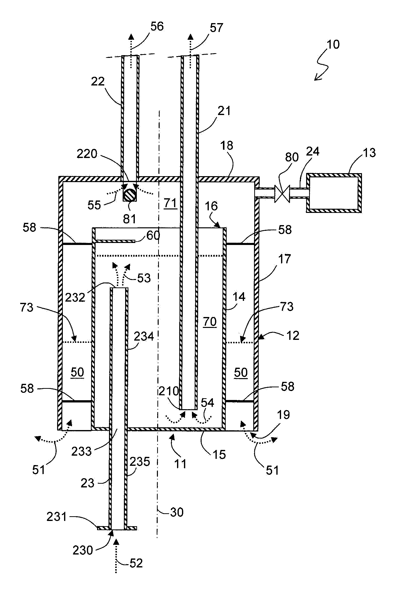
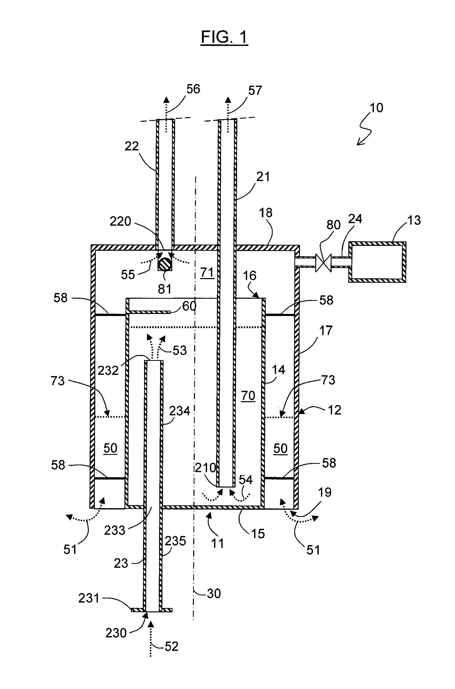
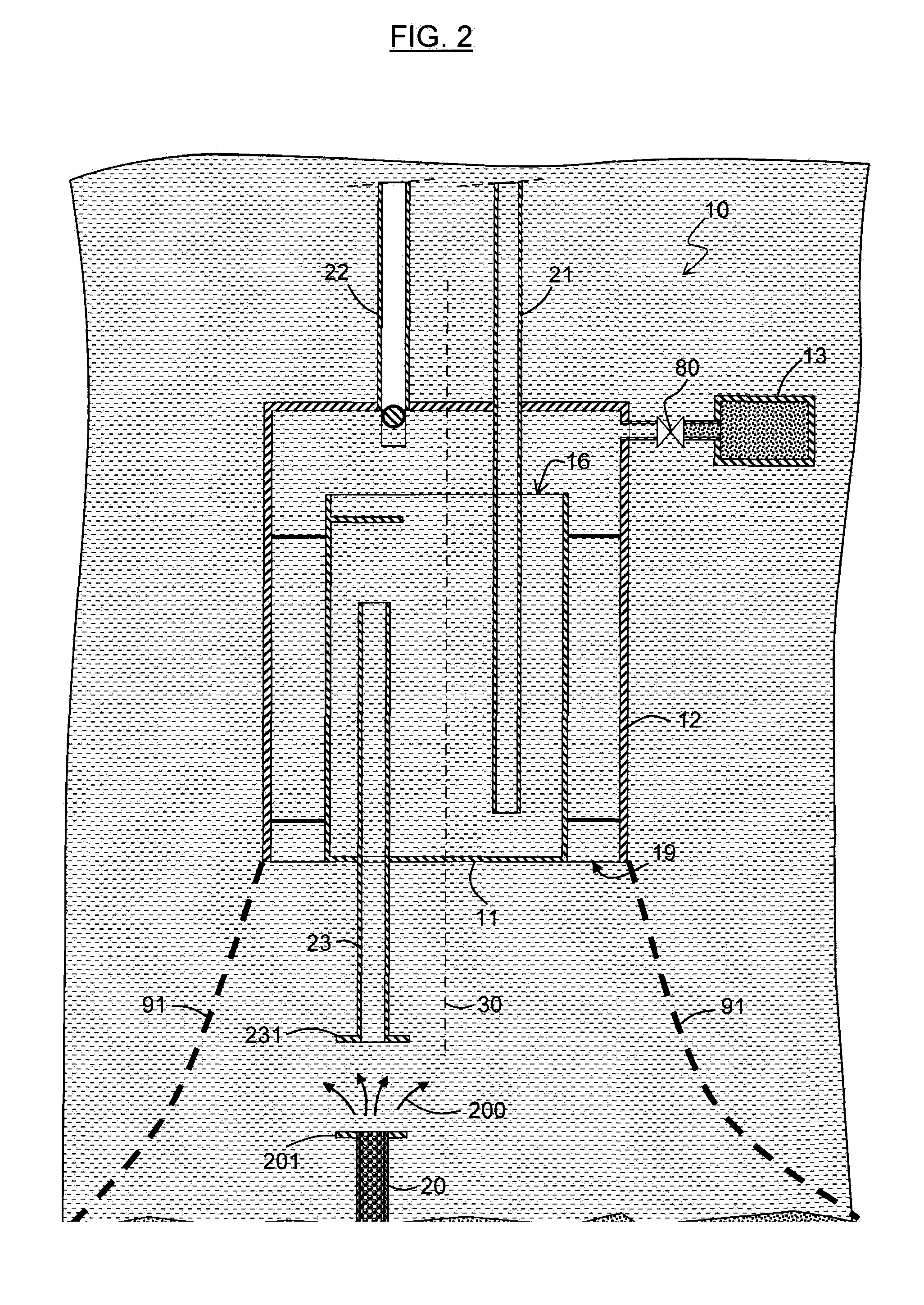
[0084]With reference to FIGS. 1 and 5 in particular, the collector device 10 is constituted essentially by two open vessels or tanks 11, 12, two or three pipes 21 to 23 leading into the tanks, and a collector structure extending under the first tank 11.

[0085]In the embodiment that corresponds to FIGS. 1 to 4 and 7, the first tank 11 has a side wall 14 of cylindrical shape extending about an axis 30 of revolution, and a bottom wall 15 closing a first longitudinal end of the wall 14, which end wall 15 is pierced by an orifice 233 for passing the collected fluid.

[0086]The second longitudinal end 16 of the wall 14 is not closed and forms a top opening for the tank 11.

[0087]In this embodiment, the second tank 12 has a side wall 17 of cylindrical shape extending about the same ...


PUM

PropertyMeasurementUnit
Timeaaaaaaaaaa
Pressureaaaaaaaaaa
Densityaaaaaaaaaa

Abstract

The invention relates in particular to a device for undersea collection of a light fluid the device comprising:a first tank that is provided with a first opening and a second opening;a second tank covering the first opening, surrounding a portion of the first tank, and provided with a third opening putting the second tank, into communication with the medium surrounding the device;connection means connecting together the first and second tanks:a first pipe opening out into the first tank in order to provide density transport of a phase of the fluid to the surface;a structure for guiding and introducing the fluid into the first tank, which structure extends inside the first tank and separates a first portion of the first tank in which the second opening is provided from a second portion of the first tank in which the open end of the first pipe extends; anda structure for collecting the fluid, which structure extends outside the first tank, is secured to the first tank, and surrounds the second opening.

Description

TECHNICAL FIELD[0001]The present invention relates to a method of collecting one or more light undersea fluids, in particular an undersea jet containing a plurality of phases of density less than that of sea water, and to a collector device for performing such a method.[0002]The invention applies in particular to collecting hydrocarbons escaping from an undersea pipe or well that is damaged and situated at great depth, and also to collecting from an undersea spring of fresh water including or mixed with a gaseous phase.[0003]Unless stated explicitly or implicitly to the contrary, in the present application, the qualifiers “light” and “heavy” are used relative to the properties of sea water; thus the term “light fluid” designates a fluid of density that is less than that of sea water.STATE OF THE ART[0004]Patent EP 1 644 589 describes a method and a device for capturing fresh water corning from an undersea spring.[0005]The device has a first pipe with a bottom end surrounding the spr...

Claims


Application Information

Patent Timeline
IPC IPC(8): E21B43/01C02F1/00E21B43/36B01D17/02
CPCE21B43/0122B01D17/0211B01D17/0214C02F2201/002E21B43/36C02F2103/08C02F1/008
Inventor CARLIN, THIERRY GILLESBECKER, PIERRE JACQUES ETIENNE
Owner NYMPHEA ENVIRONNEMENT
Learn More