
Systems and methods for improved combined cycle control

a combined cycle and control technology, applied in the direction of process and machine control, computer control, instruments, etc., can solve the problems of shortened steam piping, shortening the life of hrsg's pressure parts, and shortened life of turbomachine systems and combustion parts, etc., to achieve constant efficiency, constant efficiency, and constant load path

Active Publication Date: 2015-09-03
GENERAL ELECTRIC CO
View PDF11 Cites 14 Cited by
  • Summary
  • Abstract
  • Description
  • Claims
  • Application Information

AI Technical Summary

Benefits of technology

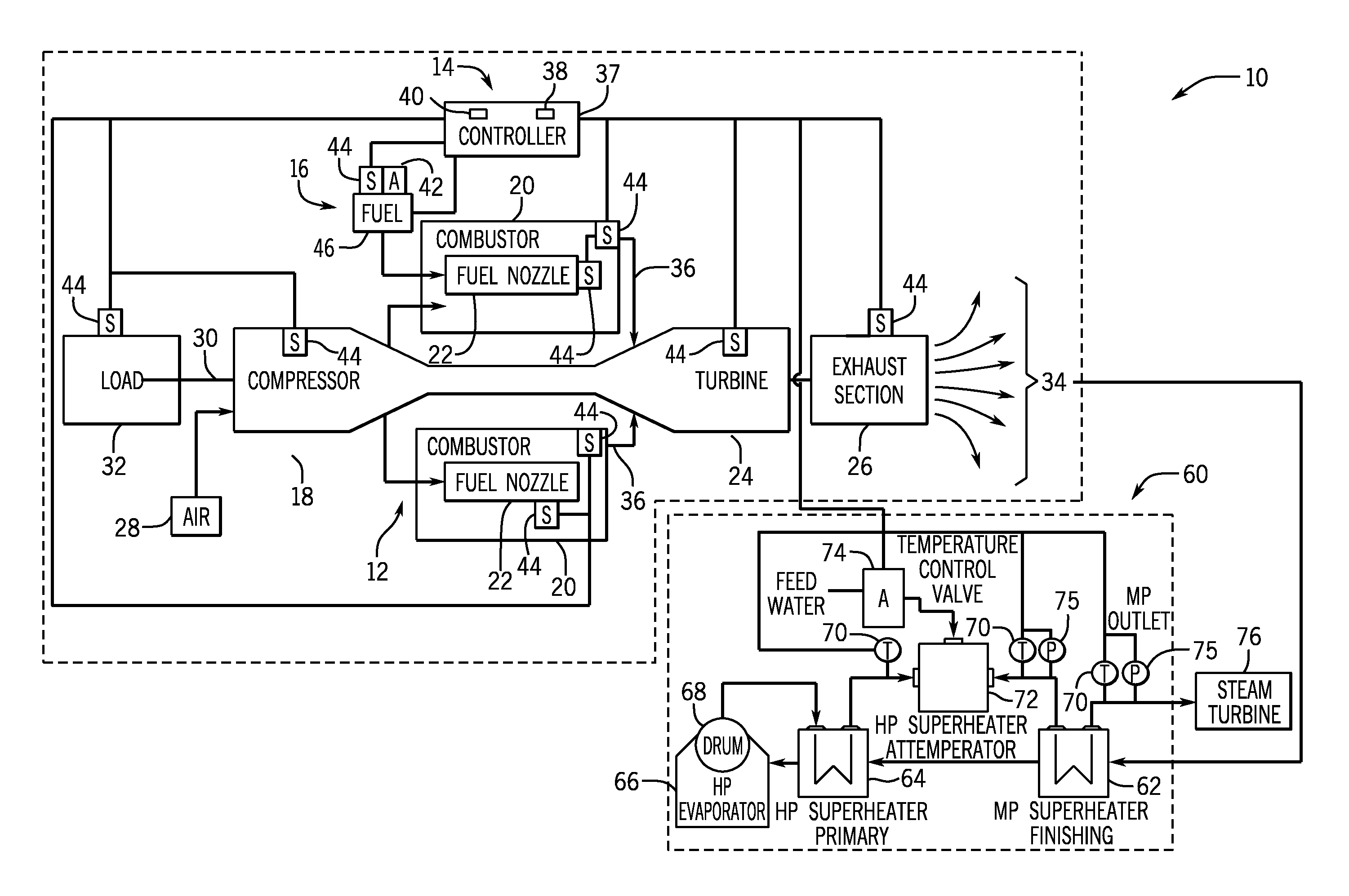
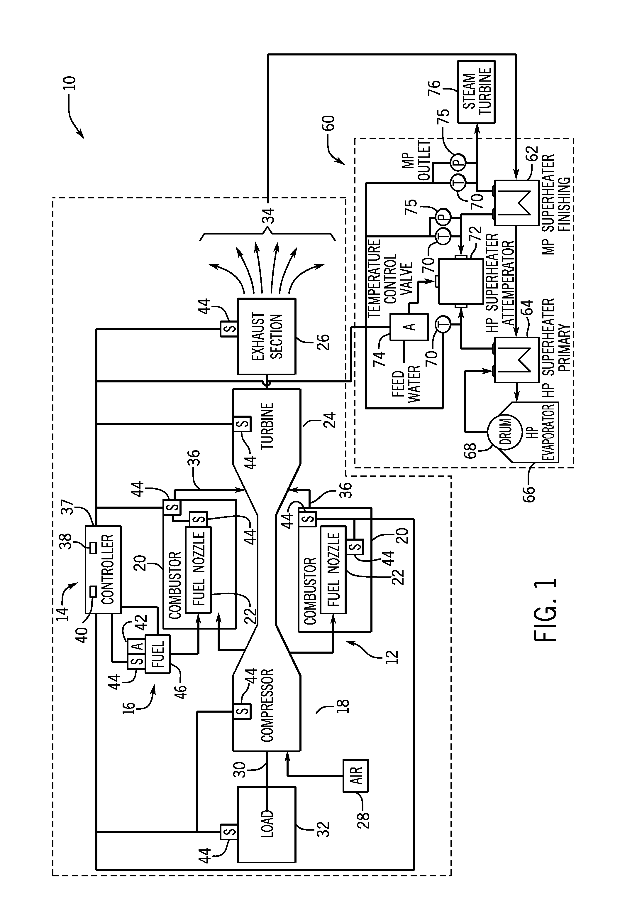
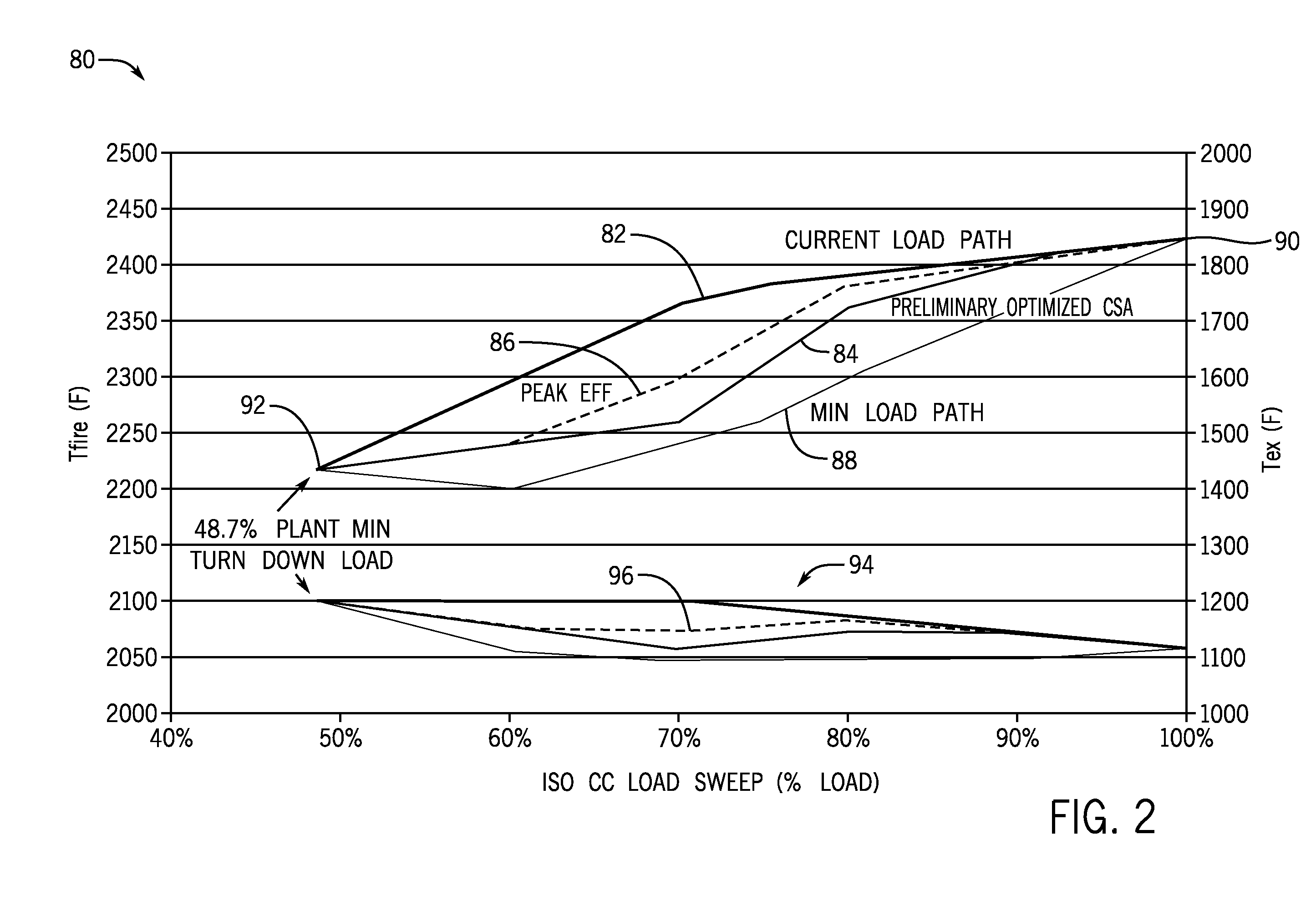
The invention is about a system, computer-readable medium, and method for controlling a turbomachine system and a bottoming cycle system using a controller that includes a memory and a processor. The controller is configured to execute a control process that receives a user input representative of a life cycle control modality and derives a load efficiency by applying a current load path, a minimum load path, a constant efficiency load path, or a combination thereof and the life cycle control modality. The control process then executes a control action based on the derived load efficiency to control the turbomachine system and the bottoming cycle system. The invention allows for efficient control of the turbomachine system and its fluidly coupled components during the life cycle control modality.

Problems solved by technology

Typical turbomachines generally run at a high firing temperature load path because of combustion system limitations and inflexibility.
However, higher firing temperature load paths may cause shorter life of a turbomachine system and its combustion parts, as well as a higher turbine exhaust temperature.
As a result, the HRSG's pressure parts and steam piping's lives are shortened.

Method used


Image

  • Systems and methods for improved combined cycle control
  • Systems and methods for improved combined cycle control
  • Systems and methods for improved combined cycle control

Examples


Embodiment Construction

[0013]One or more specific embodiments of the present invention will be described below. In an effort to provide a concise description of these embodiments, all features of an actual implementation may not be described in the specification. It should be appreciated that in the development of any such actual implementation, as in any engineering or design project, numerous implementation-specific decisions must be made to achieve the developers' specific goals, such as compliance with system-related and business-related constraints, which may vary from one implementation to another. Moreover, it should be appreciated that such a development effort might be complex and time consuming, but would nevertheless be a routine undertaking of design, fabrication, and manufacture for those of ordinary skill having the benefit of this disclosure.

[0014]When introducing elements of various embodiments of the present invention, the articles “a,”“an,”“the,” and “said” are intended to mean that ther...


PUM


Abstract

Systems and methods for improved control of a turbomachine system with a bottoming cycle system are presented. The systems and methods include a controller that utilizes modeling techniques to derive a plurality of load path curves. The controller utilizes a current load path, a minimum load path, and a constant efficiency load path. The systems and methods include a control process configured to receive a user input representative of a life cycle control modality and to execute a control action based on deriving a load efficiency by applying the current load path, the minimum load path, the constant efficiency load path, or a combination thereof, and the life cycle control modality. The control action is applied to control the turbomachine system and the bottoming cycle system fluidly coupled to the turbomachine system. Further, the life cycle control modalities may be selected by a user based upon known tradeoffs.

Description

BACKGROUND OF THE INVENTION[0001]The subject matter disclosed herein relates to controls for turbomachinery systems, such as gas turbines, and more specifically, to systems and methods for improving controls of gas turbine systems having a bottoming cycle system.[0002]Turbomachine systems may include a variety of components and subsystems participating in a process. For example, a turbomachine may include a load, fuel lines, combustors, turbine system, exhaust systems, and so forth, which generate exhaust gases. The exhaust gases generated from the turbomachine system may be fed into a bottoming cycle, such as a heat recovery steam generator (HRSG). An HRSG may convert the exhaust gas to steam, superheat the steam, and feed the steam to a steam turbine. The temperature of the exhaust gas may have an impact on the life of the turbomachine system and the HRSG, and it is dependent on the firing temperature within the turbomachine system.[0003]In a turbomachine system, the firing temper...

Claims


Application Information

Patent Timeline
Patent Type & Authority Applications(United States)
IPC IPC(8): F02C9/56G05B15/02F02G5/00
CPCF02C9/56G05B15/02F02G5/00F05D2260/821F05D2270/332F05D2270/112F02C6/18F02C9/00F05D2260/81F05D2270/71F05D2270/20F05D2270/083F05D2270/3032G05B17/02F01K5/02Y02E20/16
Inventor PANDEY, ACHALESH KUMARSHOLES, JOHN EDWARDMCDUFFIE, DWAYNE DAVIDMUNDRA, KAMLESHMAZZARO, MARIA CECILIA
Owner GENERAL ELECTRIC CO
Learn More