Intake Manifold

Inactive Publication Date: 2015-09-03
MKC FLOW
View PDF13 Cites 12 Cited by
  • Summary
  • Abstract
  • Description
  • Claims
  • Application Information

AI Technical Summary

Benefits of technology

[0016]The present invention provides an intake manifold configured to improve the overall fuel efficiency, and power and torque output of an internal combustion in engine. In some embodiments, the intake manifold comprises an asymmetrical plenum having a first end including an inlet, a closed terminal end, a top surface and a bottom surface; a flange; and a plurality of runners extending from the bottom surface of the plenum and terminating at the flange. The plenum defines an interior space in flow communication with the runners.

Problems solved by technology

However, with the onset of ever-increasing fuel costs, efficiency has been brought to the forefront of tractor-trailer technology.
Indeed, newer and more efficient engine designs are always in the pipeline, but it is not always the most economical solution to swap out equipment or send otherwise reliable and durable tractor-trailer engines to end-of-life.
Many solutions for maximizing air flow into the cylinders have been used, such as superchargers and turbochargers (or combinations of the two) but there has not been much thought put into the actual air intake manifolds of the these engines.
Such a design is prone to significant flow and pressure losses and substantial variance in airflow and pressure from one cylinder to the next as inlet a

Method used


Image

  • Intake Manifold
  • Intake Manifold
  • Intake Manifold

Examples


Embodiment Construction

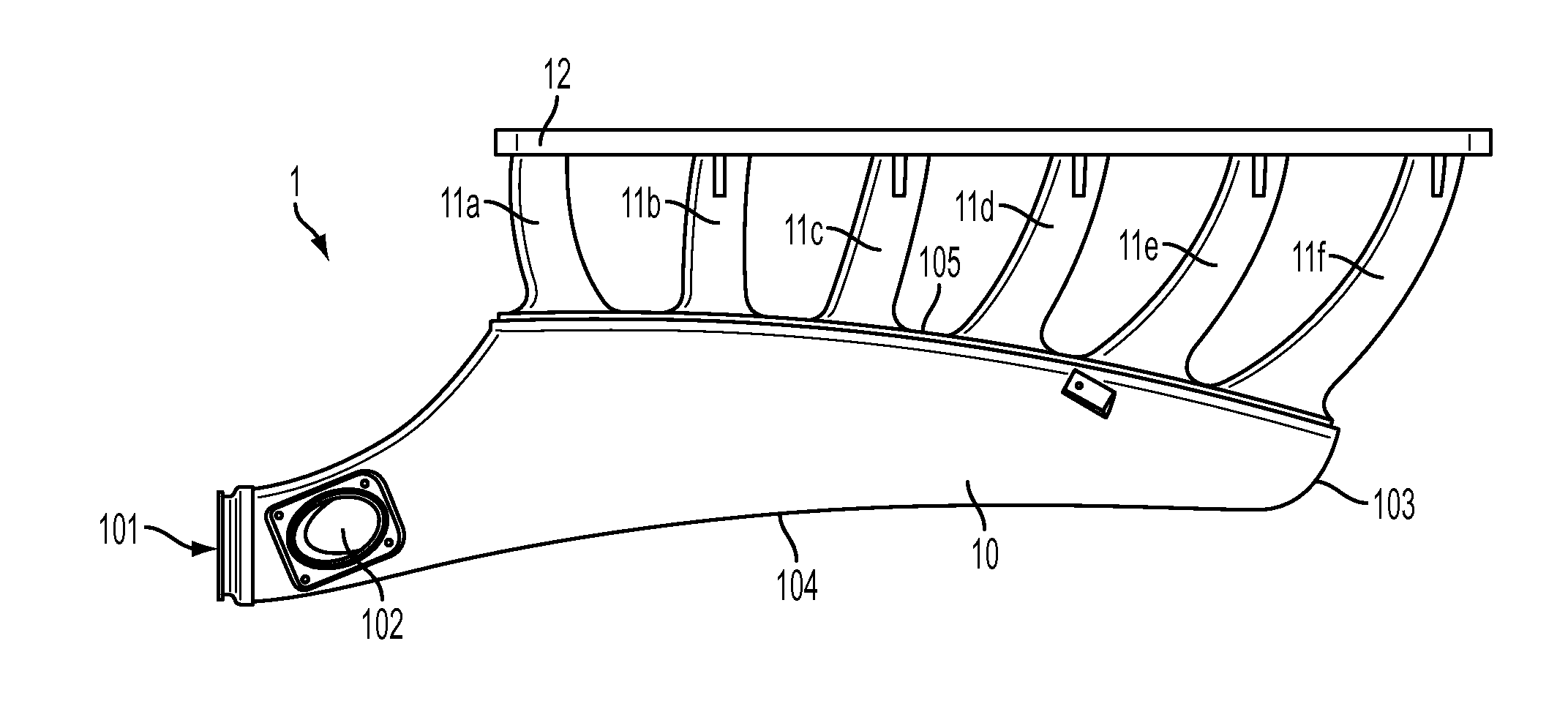
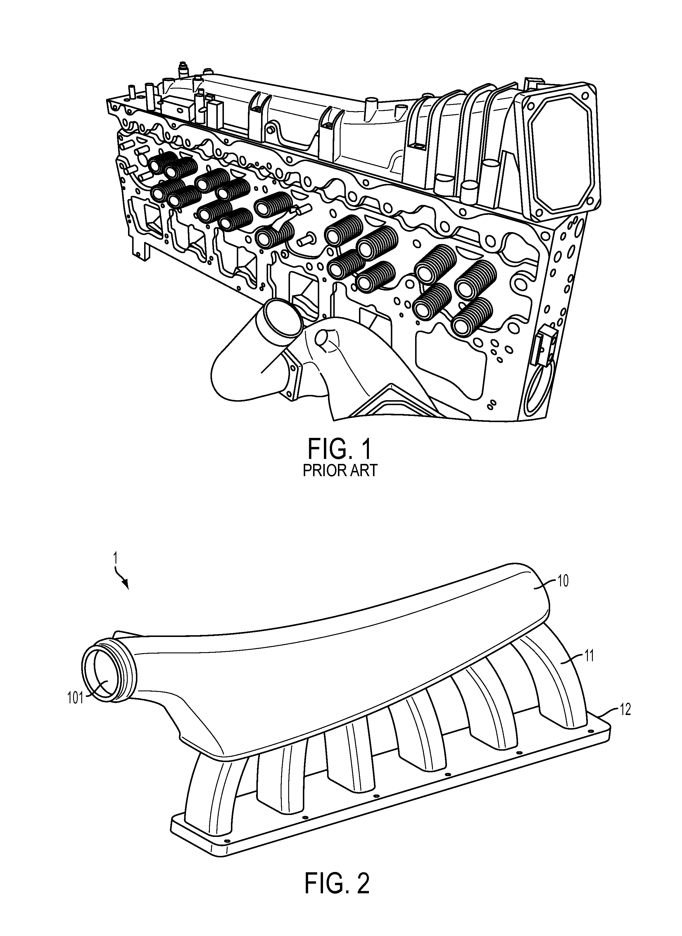
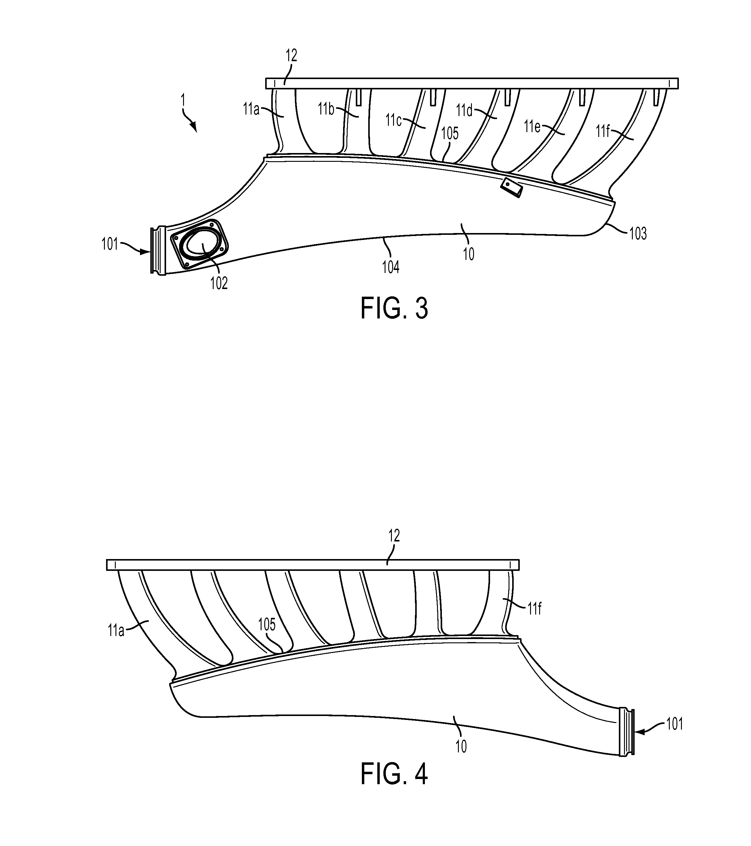
[0037]FIG. 2 is a perspective view of one embodiment of the intake manifold 1 of the present invention. Manifold 1 comprises a plenum 10, a plurality of runners 11, and a flange 12. The runners 11 are disposed longitudinally along the plenum 10 extending from and in flow communication with the plenum 10, terminating at the flange 12. In this exemplary embodiment, the manifold 1 includes six runners 11a, 11b, 11c, 11,d, 11e, and 11f corresponding to each cylinder of a six-cylinder diesel engine. The flange 12 provides mounting structure to allow the intake manifold 1 to be secured to a cylinder head of an engine, as will become more apparent throughout this disclosure. In some embodiments, the plenum 10 includes an inlet port 101 at a first end and defines an interior space that is configured to receive air from the inlet port 101 and distribute it to the runners 11. The inlet port 101, in some embodiments, receives compressed intake air from an intercooler attached to a turbocharger...


PUM


Abstract

A bolt-on replacement intake manifold has an asymmetrical plenum with a first end including an inlet, a closed terminal end, a concave top surface and a convex bottom surface; a flange; and a plurality of runners extending from the bottom surface of the plenum and terminating at the flange. The plenum defines an interior space in flow communication with the runners. The bottom surface of the plenum is wider than he top surface. The plenum initially widens from the inlet to the first runner and then begins to narrow from the first runner toward the last runner adjacent to the closed terminal end. The runners are tapered, curved, and vary in length. The intake manifold causes air to exit each of the plurality of runners at substantially the same angle. The manifold balances airflow across each runner and increases swirl inside the cylinders enhancing fuel economy, power output, and torque.

Description

CROSS REFERENCE TO RELATED APPLICATIONS[0001]N / ASTATEMENT REGARDING FEDERALLY SPONSORED RESEARCH OR DEVELOPMENT[0002]N / ABACKGROUND OF THE INVENTION[0003]1. Field of the Invention[0004]The present invention generally relates to components for internal combustion engines and more particularly to an intake manifold for use on high output engines including diesel engines found on semi-trailer trucks.[0005]2. Description of Related Art[0006]It is well established that power and torque output are of utmost importance in the field of semi-trailer and semi-tractor trailer truck engines. Certainly in many instances power and torque are maximized at the expense of fuel economy. However, with the onset of ever-increasing fuel costs, efficiency has been brought to the forefront of tractor-trailer technology. As many tractor-trailers have an average operational life expectancy exceeding ten (10) years, there is a definite need to find ways to increase the efficiency of existing engine designs. I...

Claims


Application Information

Patent Timeline
IPC IPC(8): F02M35/104
CPCF02M35/104F02M35/112F02M35/10078F02M35/10085F02M35/10098F02M35/1045F02M35/10052F02M35/10091Y02T10/12
Inventor WILSON, KEITH
Owner MKC FLOW
Why Eureka
Try Eureka