Applicator with separately produced and mounted bristle plates

a technology of bristle plates and applicators, which is applied in the field of cosmetics applicators, can solve the problems of increasing difficulty and entailing a large amount of tools

Inactive Publication Date: 2015-09-10
GEKA
View PDF7 Cites 13 Cited by
  • Summary
  • Abstract
  • Description
  • Claims
  • Application Information

AI Technical Summary

Benefits of technology

[0013]The advantage of the finger-carrying plates according to the invention lies in the fact that production is simplified even in the case of complex finger or bristle geometries.
[0014]This not only applies to a covering of tufted bristles or bristles that have been inserted individually or in small tufts, preferably without anchoring. It is obvious that a preferably plane plate can be equipped with bristles considerably quicker than is possible in the “in situ equipping” of a round or even banana-shaped, curved applicator.
[0021]In this way, a great variety of designs can be realized extremely quickly with a number of mold modules available in store.
[0022]It is preferably provided that the finger-carrying plate, due to its attachment to the applicator core, is under an internal tension that tends to restore the original first three-dimensional shape of the finger-carrying plate, at least in part. Thus, the finger-carrying plate is mounted on the applicator core with a bias. In many cases, the spring action of the finger-carrying plate can be adjusted through this bias, which increases the mobility of the bristles and results in a novel spring effect of the bristle covering during application.
[0034]Within the context of a special exemplary embodiment that is very advantageous for some cases of application, it is provided that the finger-carrying plate has, at two spaced-apart locations, positive-fit members that come to rest against each other back-to-back when the finger-carrying plate 2 assumes its second three-dimensional shape, and here then jointly form a single two-part T-strip, a single two-part dovetail strip or a single two-part beading strip, which is accommodated by a single T-groove, dovetail groove or beading groove on the core and thus retains the finger-carrying plate in its second three-dimensional shape on the applicator core. Of course, the above-mentioned strips can be configured in a segmented manner by a row of strip segments standing in alignment one behind the other; thus, they do not lose their function as “a single” strip.
[0035]A preferred embodiment provides that a ring or cap-like end part is provided which is fixed on and preferably latched to the applicator core. This end part prevents the T-connection, dovetail connection or beading connection from being pulled out of the applicator core.

Problems solved by technology

However, the production of a bristle or finger covering of fingers protruding radially all around from a core provided with a round, elliptical or polygonal cross section entails a very considerable expenditure as regards tools.
Because of its special kinematics, this injection mold only has a finite life, because, as the frictional wear on the surfaces sliding along each other during opening and closing increases, it gets more difficult, despite the high injection pressures due to the delicate structures, to make the injection mold so perfectly tight again after each opening process that a formation of burrs at the separation points does not occur.

Method used


Image

  • Applicator with separately produced and mounted bristle plates
  • Applicator with separately produced and mounted bristle plates
  • Applicator with separately produced and mounted bristle plates

Examples


first complete exemplary embodiment

[0139]FIGS. 13 to 15 show a first complete exemplary embodiment that illustrates how the above-described finger-carrying plates 2 are used in order to produce an applicator 1, and in particular a cosmetics applicator.

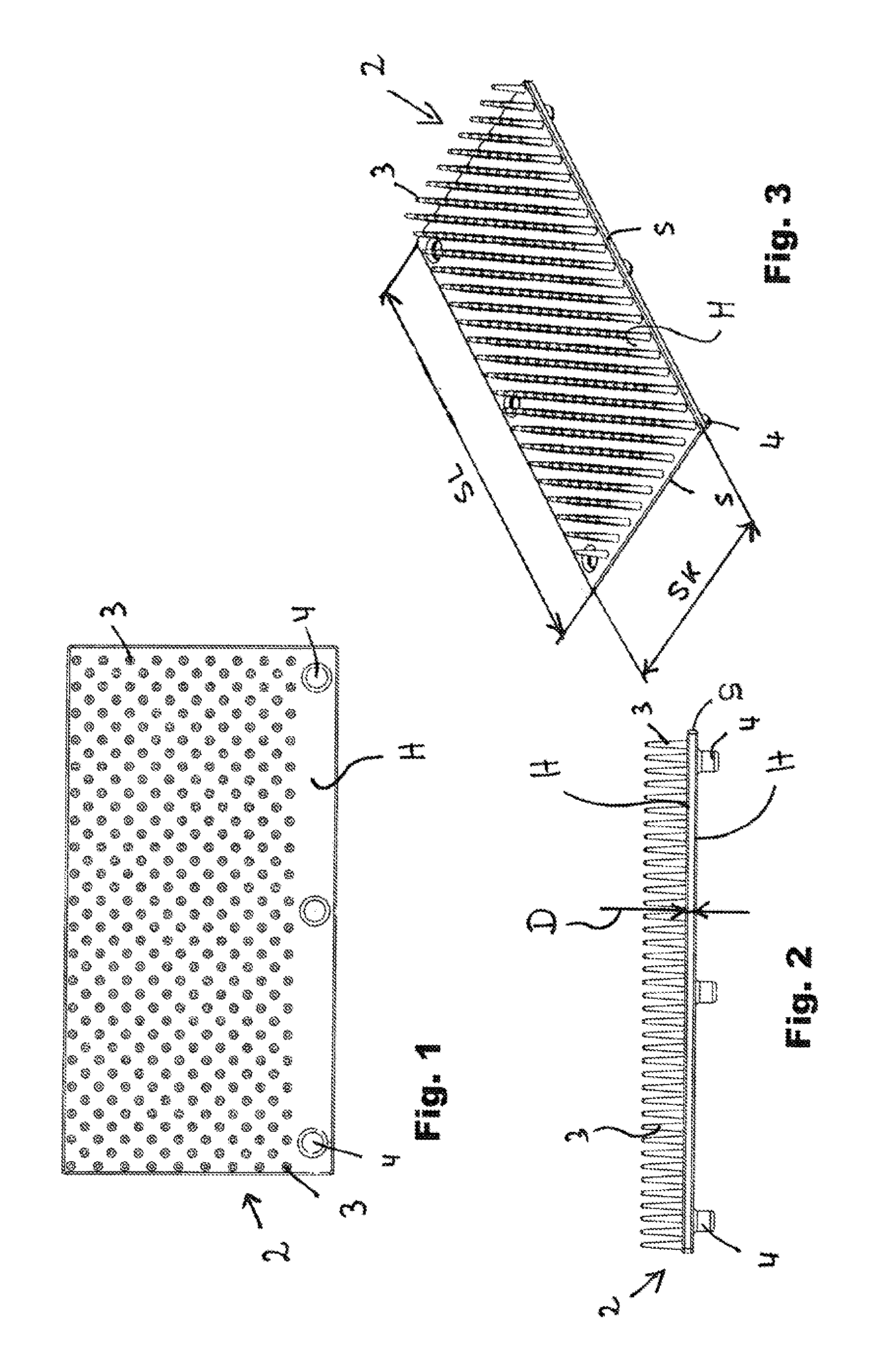
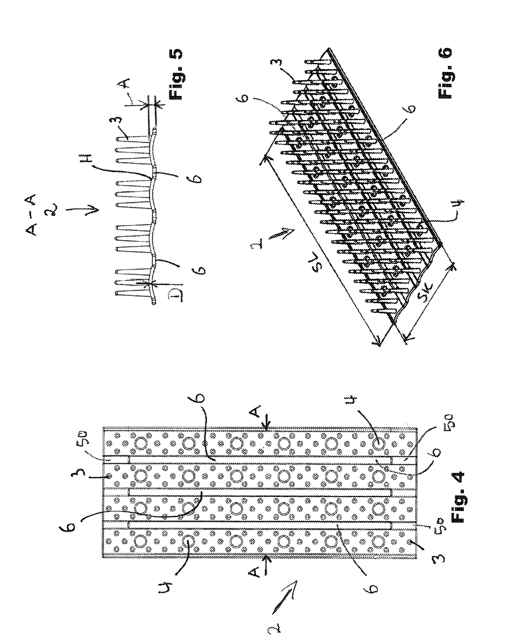
[0140]Preferably, a finger-carrying plate 2 as is shown by FIG. 13 is used as the starting point, wherein, however, finger-carrying plates with a different design can also be used. In any case, the statements in the introduction pertaining to the finger-carrying plates apply mutatis mutandis.

[0141]Here, the finger-carrying plate 2 has a tongue-like shape, i.e. its long lateral edges SL are larger by at least the factor 4 than its short lateral edges SK.

[0142]The finger-carrying plate 2 is equipped with a field of fingers 3 in which the fingers respectively form rows of fingers aligned one behind the other in the longitudinal direction and in the transverse direction extending perpendicularly thereto. Here, the fingers are preferably all oriented parallel with regard to ...

second complete exemplary embodiment

[0153]FIGS. 16 and 17 show a second complete exemplary embodiment of the invention.

[0154]A finger-carrying plate 2 as it is shown by FIG. 16 is used for this exemplary embodiment. In principle, this finger-carrying plate 2 corresponds to the finger-carrying plate already shown by FIG. 13, so that reference can be made to the explanations given there.

[0155]The only point to note is that the fingers are not arranged in lines in the longitudinal and transverse direction, but are distributed irregularly. However, they may also be arranged in lines also in this case, just like in the preceding exemplary embodiment. Conversely, the type of arrangement of the fingers here can of course also be chosen for the preceding exemplary embodiment.

[0156]FIG. 16 again shows the finger-carrying plate 2 in its first three-dimensional shape, which it assumes immediately after its production.

[0157]FIG. 17 shows the finished applicator 1.

[0158]In this case, an applicator core 8 is used again which may be...

third complete exemplary embodiment

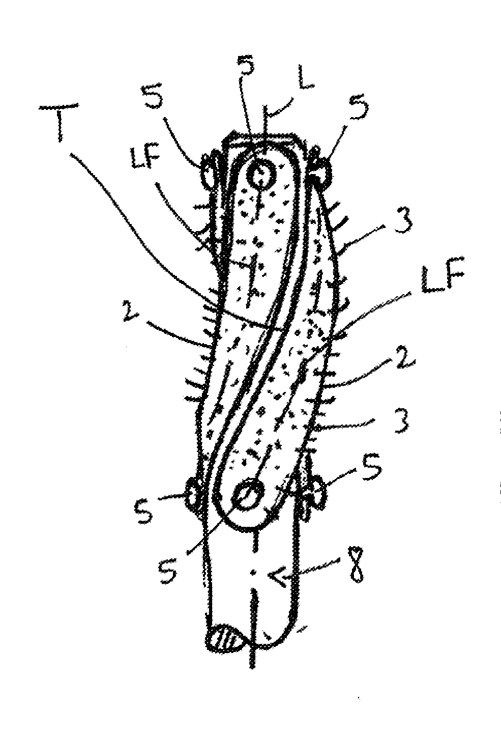
[0164]FIG. 18 shows a third complete exemplary embodiment.

[0165]Preferably, finger plates 2 as they have already been described above for the two preceding exemplary embodiments are again used within the context of this third complete exemplary embodiment; also see FIGS. 13 and 16. The statements there thus also apply here.

[0166]The special feature in this exemplary embodiment is that the longitudinal axes LF of the finger-carrying plates 2 here extend in a helical shape around the longitudinal axis L of the applicator core 8. In contrast to the similar exemplary embodiment already discussed above, each finger-carrying plate does not encircle the core part 9 completely, but extends only over an angle of ≦190 °, and better of ≦100 °, around the core part 9. Starting from their first three-dimensional shape shown in FIG. 16, the finger-carrying plates have been brought into a corresponding second three-dimensional shape.

[0167]Also in this case, fixation is effected by retaining organs...


PUM


Abstract

A cosmetics applicator with an applicator core and a finger-carrying elastic plate, which has a first three-dimensional shape prior to being united with the core, wherein the finger-carrying plate is attached to the applicator core in such a way that a second three-dimensional shape, which deviates from the first three-dimensional shape, is thereby forced upon it.

Description

FIELD OF THE INVENTION[0001]The invention relates to a cosmetics applicator with an applicator core and a finger-carrying elastic plate, which has a first three-dimensional shape prior to being united with the core, and a method for producing the same.BACKGROUND OF THE INVENTION[0002]Cosmetics applicators are typically produced as so-called wire core applicators, by a number of filaments being inserted between the two legs of a U-shaped wire and the two wire legs then being twisted. The filaments are thus distributed in a helical shape between the wire legs and clamped firmly.[0003]However, different applicators are required for different cases of application. To satisfy this requirement to some degree, such wire core brushes are subsequently cut or thinned out. The spectrum of the variations that can thus be attained, however, leaves something to be desired.[0004]Therefore, a transition has been made in the past decade to producing so-called injection-molded cosmetics applicators, ...

Claims


Application Information

Patent Timeline
Patent Type & Authority Applications(United States)
IPC IPC(8): A45D40/26
CPCA45D40/262A45D40/26A46B3/16A46B7/042A46B9/021A46B2200/1053
Inventor HAUGER, CHRISTIAN
Owner GEKA
Why Eureka
Try Eureka