Device for breaking glass

a glass and glass fragment technology, applied in the field of improved glass devices, can solve the problems of affecting the operation of operators, affecting the operation of glass current separation, and causing noise from trucks collecting bottles, so as to reduce the sharpness of the edges of glass fragments, reduce the risk of operator use, and be quiet and safe to handle

Active Publication Date: 2015-09-10
GLASSBUSTERS
View PDF4 Cites 3 Cited by
  • Summary
  • Abstract
  • Description
  • Claims
  • Application Information

AI Technical Summary

Benefits of technology

[0027]The system can produce glass fragments, that have few or no sharp edges and therefore creates a product that is relatively safe to handle without the need for protection. The edges of the glass are ‘blunt’ due to the impact of the rotatable member on the glass and the way in which the glass is shattered and then expelled. The particles contacting one another assists in reduces the sharpness of the edges of the glass fragments.
[0028]It is desirable that the glass disposal system comprises a bottle receiving conduit as disclosed herein at its first end. Combining the bottle receiving conduit of the present invention with the glass breaking device of the present invention provides a glass disposal system that is relatively quiet and safe for the operator to use. The silencing mechanism of the conduit combined with the safety and airflow of the device provides a system that can be used in environments where noise must be kept to a low level.
[0029]Advantageously, the system further comprises a method of removing the glass fragments from the hopper. In one construction, the method of removing the glass fragments from the hopper comprises a receptacle that attaches to the valve on the hopper. Providing containers or bags, such as sand bags, that attach to the valve allows for conveniently sized bodies filled with glass fragments to be produced. This allows them to be easily loaded for removal from site and because it is significantly compact compared to the unbroken glass it can be removed using a small vehicle or more glass can be fitted onto a regular vehicle.
[0030]In an alternative construction the method of removing the glass fragments from the hopper comprises a hose for attaching to the valve of the hopper and a suction system to suck the fragments through the hose. Using a hose and a suction system, the glass fragments can be moved from the hopper to a vehicle for transportation away from site. This reduces the labour required for moving the glass manually and allows fur a quick and easy removal system. The hosing, or pipe work, required may be permanently installed and the hose to remove the glass from site attached to the end of the installed hosing. It may also be desirable to remove the glass from the hopper to an external bin that can then be taken away for emptying. Alternatively, the glass breaking device may be located outside the building so that the hopper can be quickly and conveniently emptied without requiring access to the building. This allows for collection out of normal business hours.
[0031]It is desirable that the first location is on one floor of a building and the second location is on a different floor of the building. By having the inlet to the conduit on once floor and the breaking device on another floor, the noise levels can be reduced further at the inlet end of the conduit and the device can operate in an environment that is easily accessible for emptying without interfering with customer service. For example, the conduit inlet may be installed in a bar on the ground floor of a building with the breaking device in the cellar thereof. This allows the bar staff to immediately put bottles into the conduit and for them to be processed in the cellar where noise is not such an issue. Additionally, the device hopper can be empties mid-shift without needing to clear space around the bar Additionally, by using the hopper, the value on the hopper can be opened and the glass fragments removed while the glass breaking device is still operating. This reduces the ‘down time’ during emptying and allows continual service, or close thereto, during a shift. The system is of particular use in bars, restaurants and other venues where a high number of glass bottles are used.
[0032]Additionally, the glass breaking device may be used as a stand-alone unit to reduce the volume taken up by the waste bottles at a particular location, thereby increasing the efficiency when the glass is removed. The removes the need to install the device between floors of a building and allows the device to be used without the conduit. As an example, this may be especially useful at festivals or in large venues with more than one bar where it is not practical to install a permanent system. In such a situation, the glass can be broken into small particles and stored in a hopper, thereby using less storage space. Additionally, the hopper may be emptied by way of a suction device that transports the broken glass into a portable hopper. This allows one larger hopper to be filled by smaller hoppers connected to devices scattered around a venue.

Problems solved by technology

Bars and restaurants create a large amount of waste in the form of bottles and other glass articles.
Where glass crushing devices are used, they usually have to be operated either away from customers and / or after closing time of the premises due to the noise produced during use.
Additionally, the trucks collecting the bottles also create a large amount of noise, especially when tipping a large number of whole bottles into a container.
This can be particularly irritating early in the morning or late at night.
One problem with crushed glass is that it can contain sharp projections that can cut skin.
Additionally, during the crushing process, there may be shards of glass that are projected out of the crushing device back towards a user, thereby putting the user at risk of being hit by high-speed glass.
Even where the risk of glass being projected back towards the user is low, glass dust may be expelled by the device and breathed in by a user.
A further disadvantage of traditional methods of dealing with commercial glass waste is that the bottles are often stored behind the bar and then moved to another location at the end of the night when the customers have left.
This increases the amount of time that the staff are required for a shift and can lead to back problems if the staff member has bad lifting technique.

Method used


Image

  • Device for breaking glass
  • Device for breaking glass
  • Device for breaking glass

Examples


Embodiment Construction

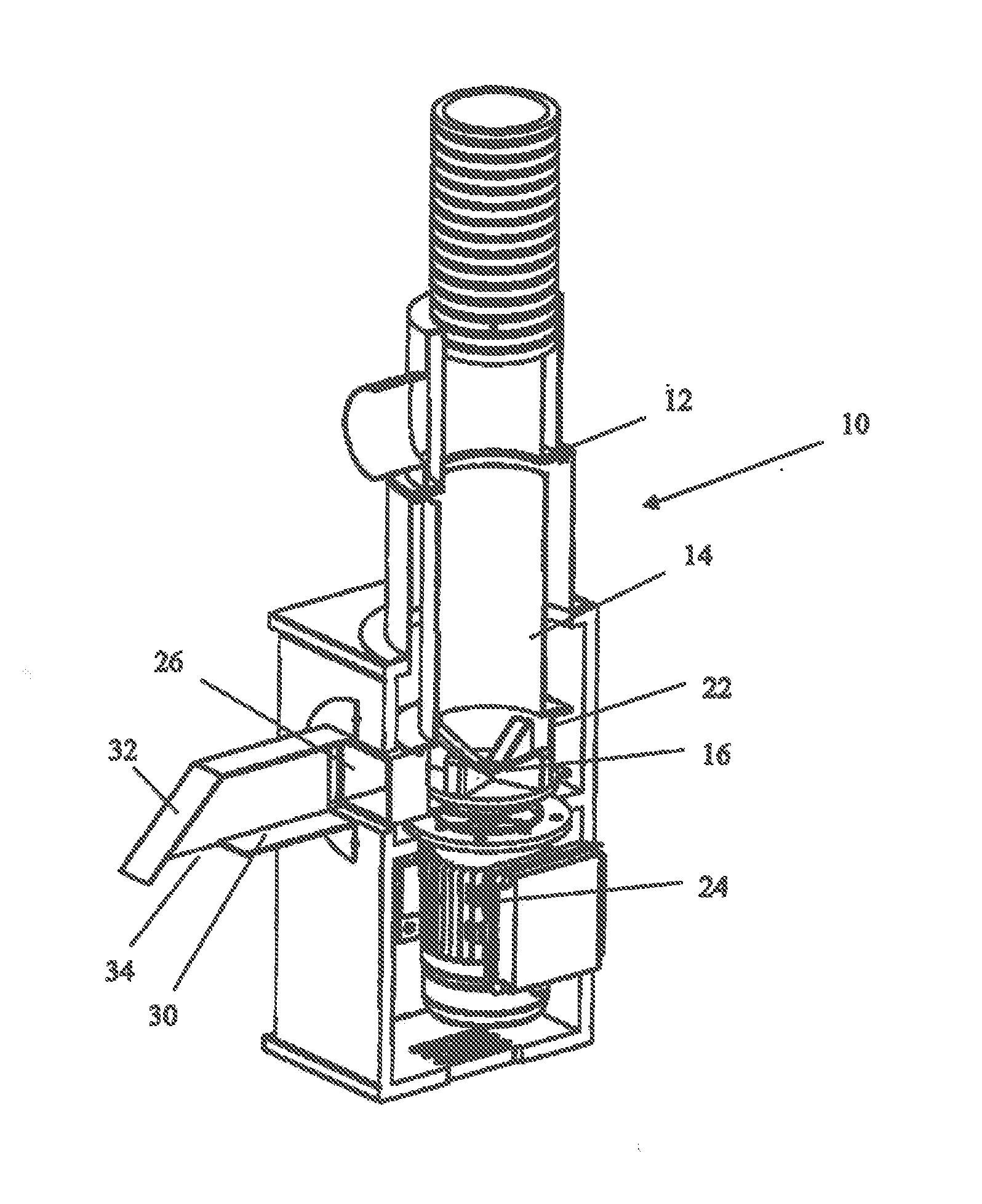
[0043]The device disclosed herein is intended primarily, although not exclusively to be used in bars, and especially bars having a cellar beneath the bar—either directly beneath or to one side—to enable glass bottles to be disposed of readily and in a form convenient for transportation and recycling. However, the device is not limited to such an arrangement and can be used for example between floors of a building or also between a work surface and under bar. The bottles, in order to reduce the volume required for their storage prior to disposal and / or transport are broken into small pieces. Although the production of glass powder during the process is inevitable, the amount of powder is ideally as low as possible and the majority of the glass particles should have a diameter of from 5 mm-20 mm.

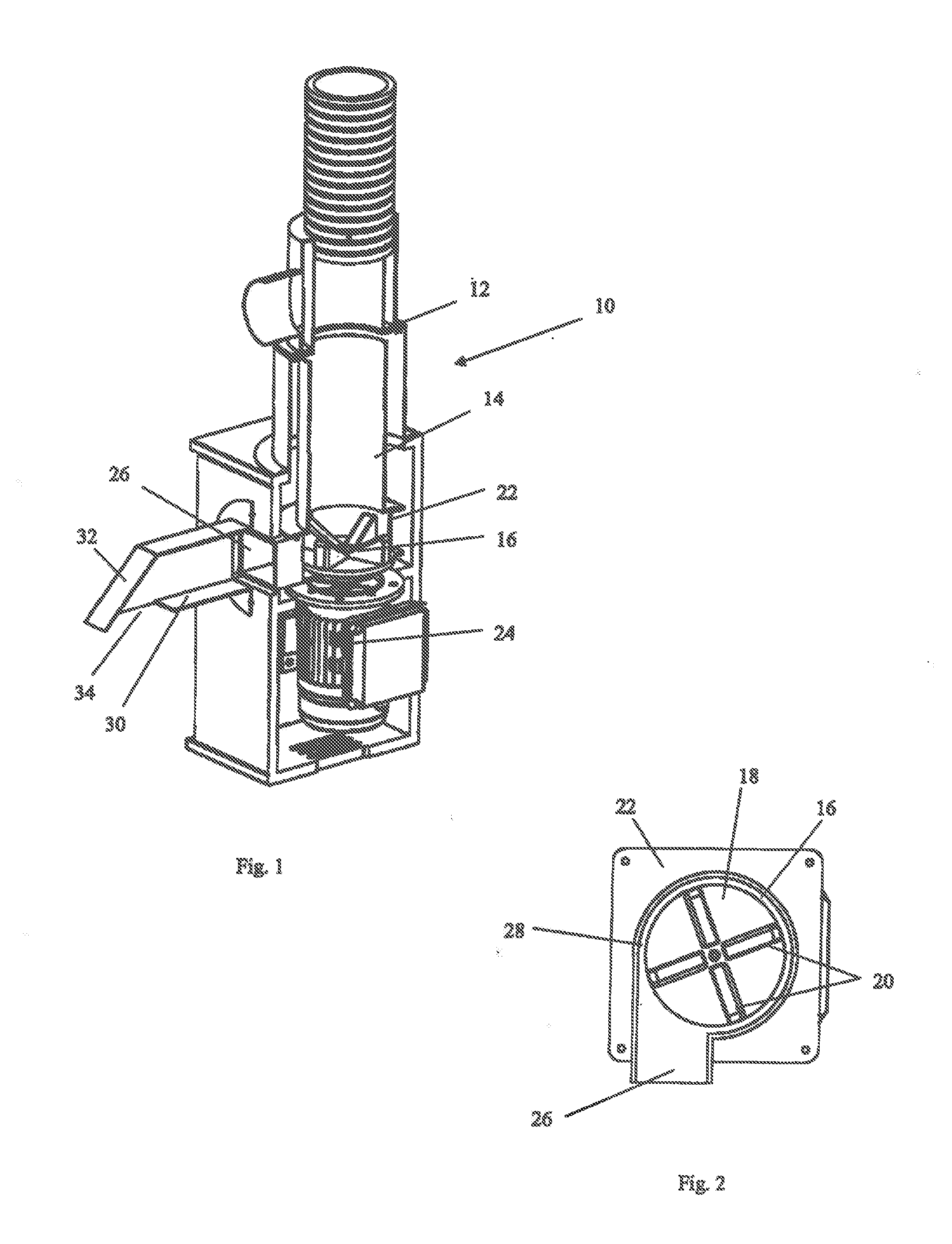
[0044]FIGS. 1, 4 and 7 show a glass breaking device 10, comprising an inlet 12 in the form of a substantially vertical circular conduit, which leads to an enclosed breaking chamber 14. At the ...


PUM


Abstract

The invention is directed to a glass disposal system. A device (10) for breaking glass articles is provided, which comprises an inlet (12) and an outlet (26) in fhrkl communication with one another and having a rotating member (16) interposed therebetween. The rotating member (16) is attached to, and capable of being rotated by, a motor (24). The inlet (12) to the device (10) opens onto the rotatable member (16) and the outlet (26) is substantially tangential to the rotatable member (16). The rotatable member (16) comprises portions to create an overall flow of air from the inlet (12) towards the outlet (26), and subsequently expels the particles of the broken object away from the rotatable member (16) through the outlet (26). The invention extends to a conduit (60) for the system.

Description

FIELD OF THE INVENTION[0001]This invention relates to an improved device for breaking glass and glass-like materials, including ceramic materials, into smaller particles, which can be more readily stored.BACKGROUND TO THE INVENTION[0002]Bars and restaurants create a large amount of waste in the form of bottles and other glass articles. Generally, these are stored in large bins and then disposed of by collection in trucks. The mass of glass which a truck is able to take away is dictated by the space available rather than the weight because the majority of the load is air contained within the glass: for example in the internal volume of an intact bottle. Trucks can transport up to eight times as much crushed glass as complete bottles. Therefore, it is advantageous to transport crushed glass rather than whole bottles.[0003]Where glass crushing devices are used, they usually have to be operated either away from customers and / or after closing time of the premises due to the noise produce...

Claims


Application Information

Patent Timeline
Patent Type & Authority Applications(United States)
IPC IPC(8): B02C19/00B02C23/34B02C23/28
CPCB02C19/0087B02C23/34B02C23/28Y02W30/60
Inventor WEBB, IANANCKETILL, PETER
Owner GLASSBUSTERS
Why Eureka
Try Eureka