Leak inspection device, leak inspection method, and leak inspection program
a leak inspection and leak detection technology, applied in the direction of fluid tightness measurement, instruments, machines/engines, etc., can solve the problems of manpower inspection, pipe breakage, risk and great effort, and achieve the effect of small energy consumption
- Summary
- Abstract
- Description
- Claims
- Application Information
AI Technical Summary
Benefits of technology
Problems solved by technology
Method used
Image

Examples
first exemplary embodiment
Outline
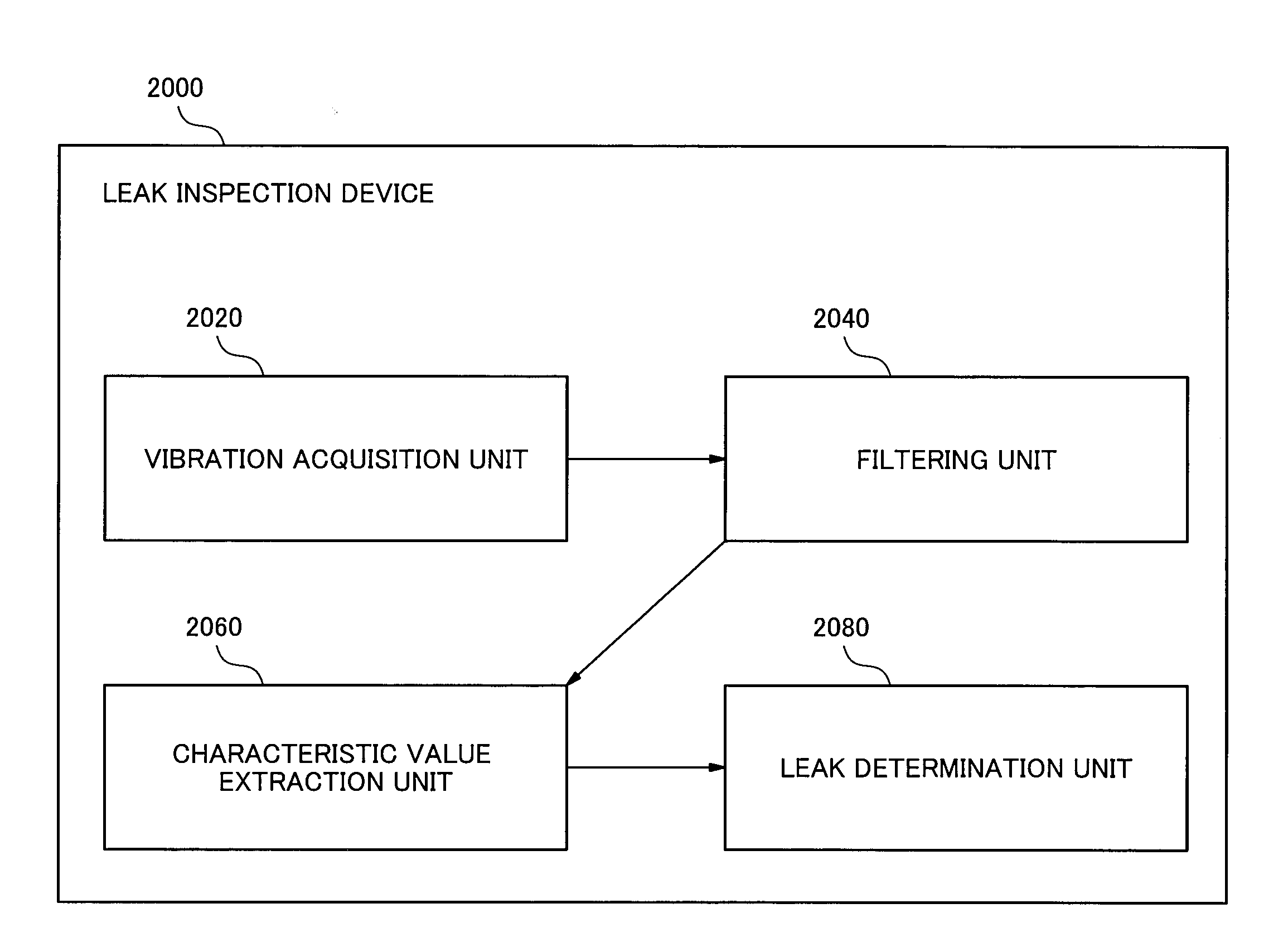
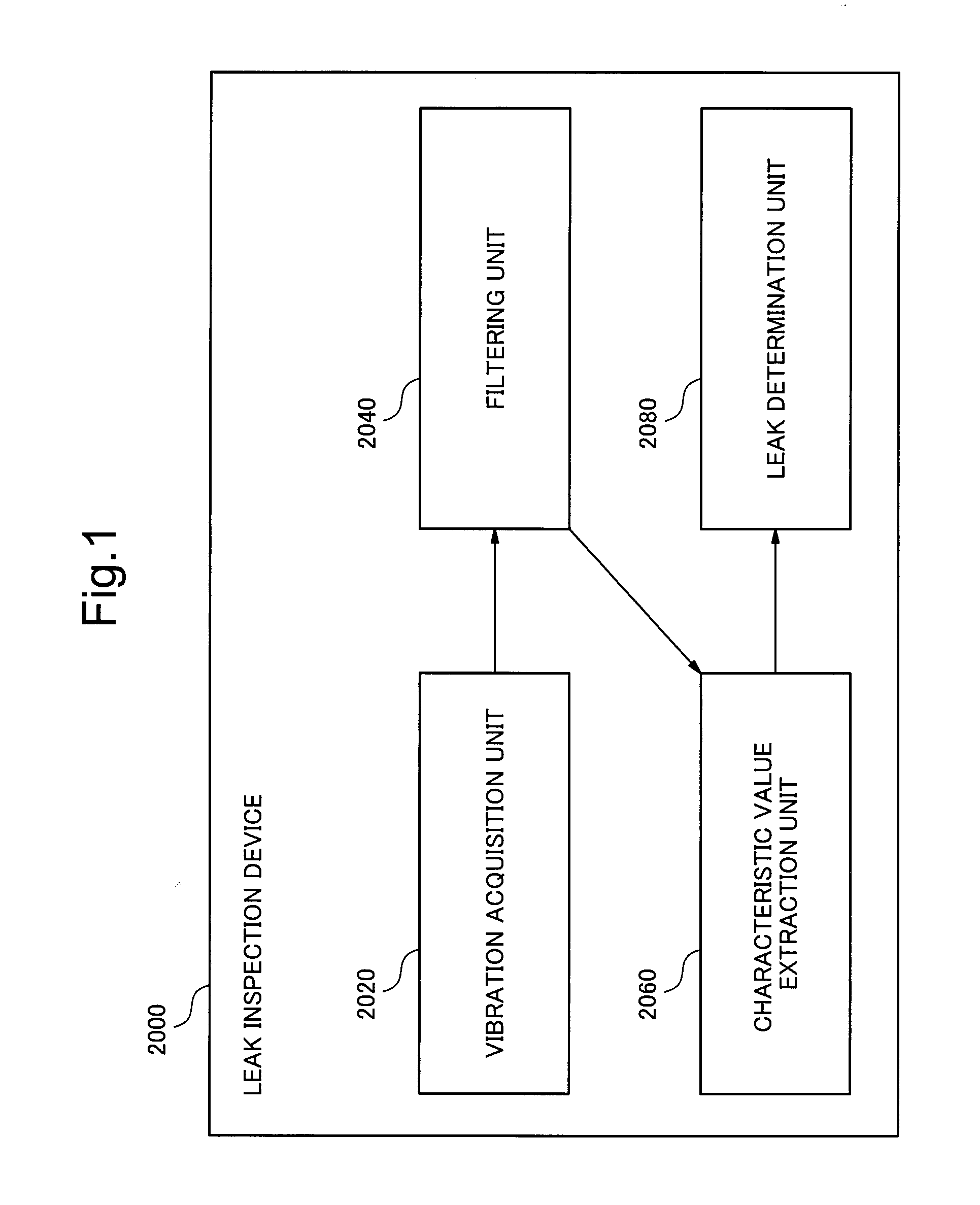
[0041]FIG. 1 is a block diagram illustrating a leak inspection device 2000 according to a first exemplary embodiment. In FIG. 1, arrows express the flow of information.
[0042]The leak inspection device 2000 has a vibration acquisition unit 2020. The vibration acquisition unit 2020 obtains a signal indicative of a vibration of a pipe or of a vibration propagating from a pipe.
[0043]The leak inspection device 2000 has a filtering unit 2040. The filtering unit 2040 extracts a signal of a predetermined frequency band from a signal obtained by the vibration acquisition unit 2020. Hereinbelow, to distinguish a signal obtained by the vibration acquisition unit 2020 and a signal after the filtering unit 2040 performs a filtering process from each other, the former signal will be described as a source signal, and the latter signal will be described as an extraction signal.
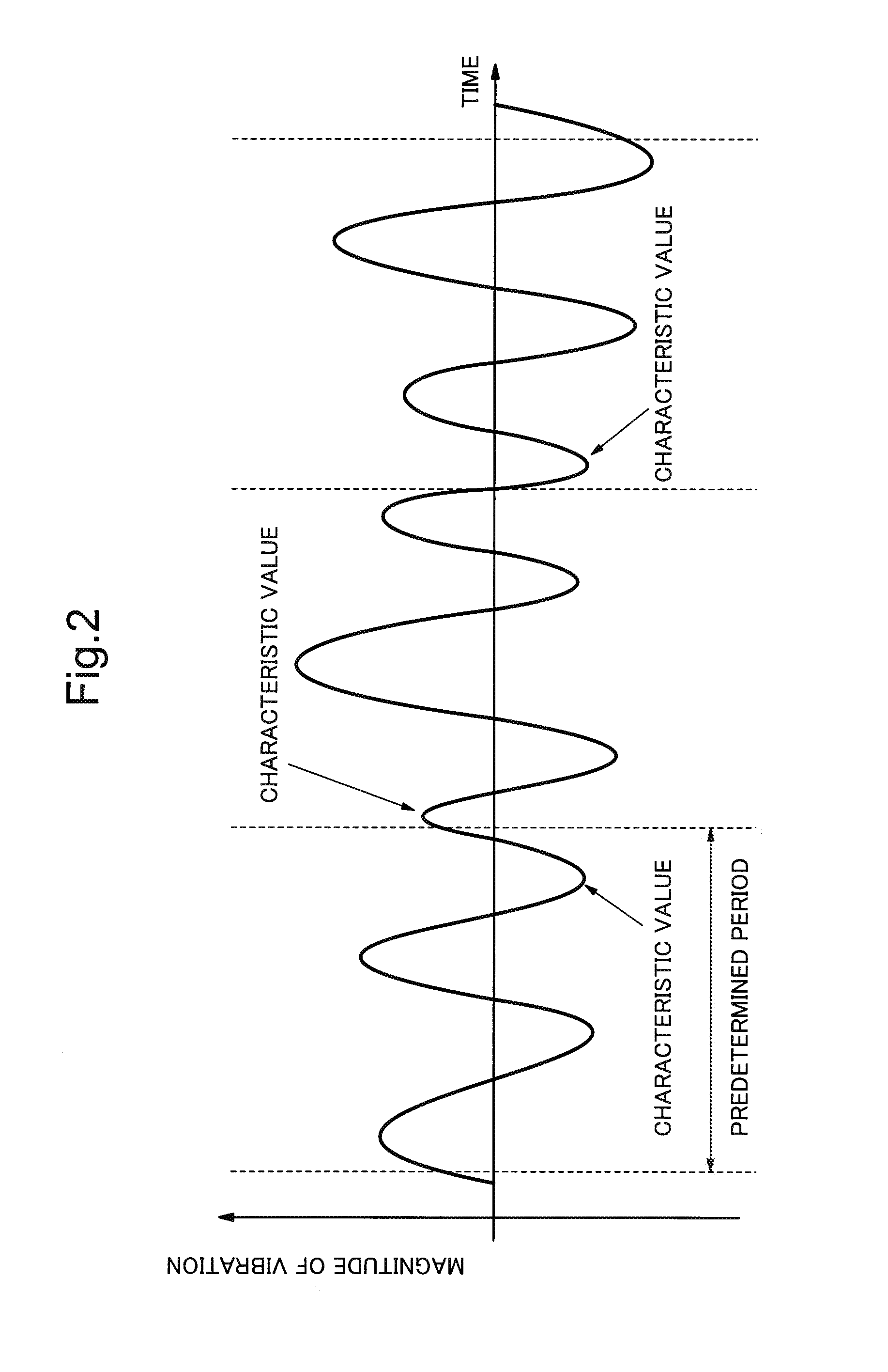
[0044]The leak inspection device 2000 has a characteristic value extraction unit 2060. The characteristic value extr...
first modification
[0073]The leak inspection device 2000 according to the exemplary embodiment may have a plurality of filtering units 2040 whose predetermined frequency bands are different from each other and a plurality of characteristic value extraction units 2060 corresponding to the filtering units 2040. The configuration of the leak inspection device 2000 in this case is, for example, the configuration illustrated in the block diagram of FIG. 5. The leak inspection device 2000 in this aspect will be called the leak inspection device 2000 of the first modification.
[0074]The leak inspection device 2000 of the first modification extracts a plurality of extraction signals of different frequency bands from a single source signal by the plurality of filtering units 2040. The characteristic value extraction unit 2060 extracts a characteristic value from an extraction signal extracted by the corresponding filtering unit 2040.
[0075]The leak determination unit 2080 of the leak inspection device 2000 of th...
second exemplary embodiment
Outline
[0078]FIG. 6 is a block diagram illustrating a leak inspection device 2000 according to a second exemplary embodiment. Unless otherwise described, in the functional blocks illustrated in FIG. 6, the functional blocks having the same numerals as those in FIG. 1 have the same functions as the functional blocks of FIG. 1. Therefore, the description of those functional blocks will not be repeated.
[0079]The leak inspection device 2000 of the exemplary embodiment further includes a leak amount information acquisition unit 2100 and a leak amount calculating unit 2120. The leak amount information acquisition unit 2100 obtains leak amount information as information indicating association between the above-described determination index value and a leak amount. The leak amount information is, for example, information expressing a calibration curve indicative of the relation between the determination index value and the leak amount illustrated in FIG. 7. Alternatively, the leak amount in...
PUM
 Abstract
Description
Claims
Application Information
 - R&D
- Intellectual Property
- Life Sciences
- Materials
- Tech Scout
- Unparalleled Data Quality
- Higher Quality Content
- 60% Fewer Hallucinations
Browse by: Latest US Patents, China's latest patents, Technical Efficacy Thesaurus, Application Domain, Technology Topic, Popular Technical Reports.
© 2025 PatSnap. All rights reserved.Legal|Privacy policy|Modern Slavery Act Transparency Statement|Sitemap|About US| Contact US: help@patsnap.com