Frequency-stabilized random distributed feedback fiber ring laser with low intensity noise

a fiber ring laser and random distributed feedback technology, which is applied in the direction of laser details, electrical equipment, active medium shape and construction, etc., can solve the problems of degrading the performance of the rdfb laser, high intensity noise and frequency, etc., and achieves the reduction of frequency jitter and intensity noise, the effect of reducing the relative intensity noise of the fiber ring laser and reducing the frequency jitter

Active Publication Date: 2015-09-10
UNIVERSITY OF OTTAWA
View PDF3 Cites 16 Cited by
  • Summary
  • Abstract
  • Description
  • Claims
  • Application Information

AI Technical Summary

Benefits of technology

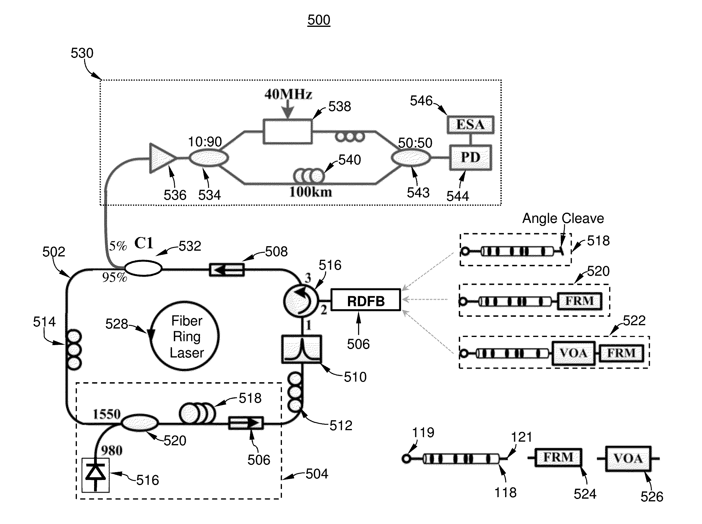
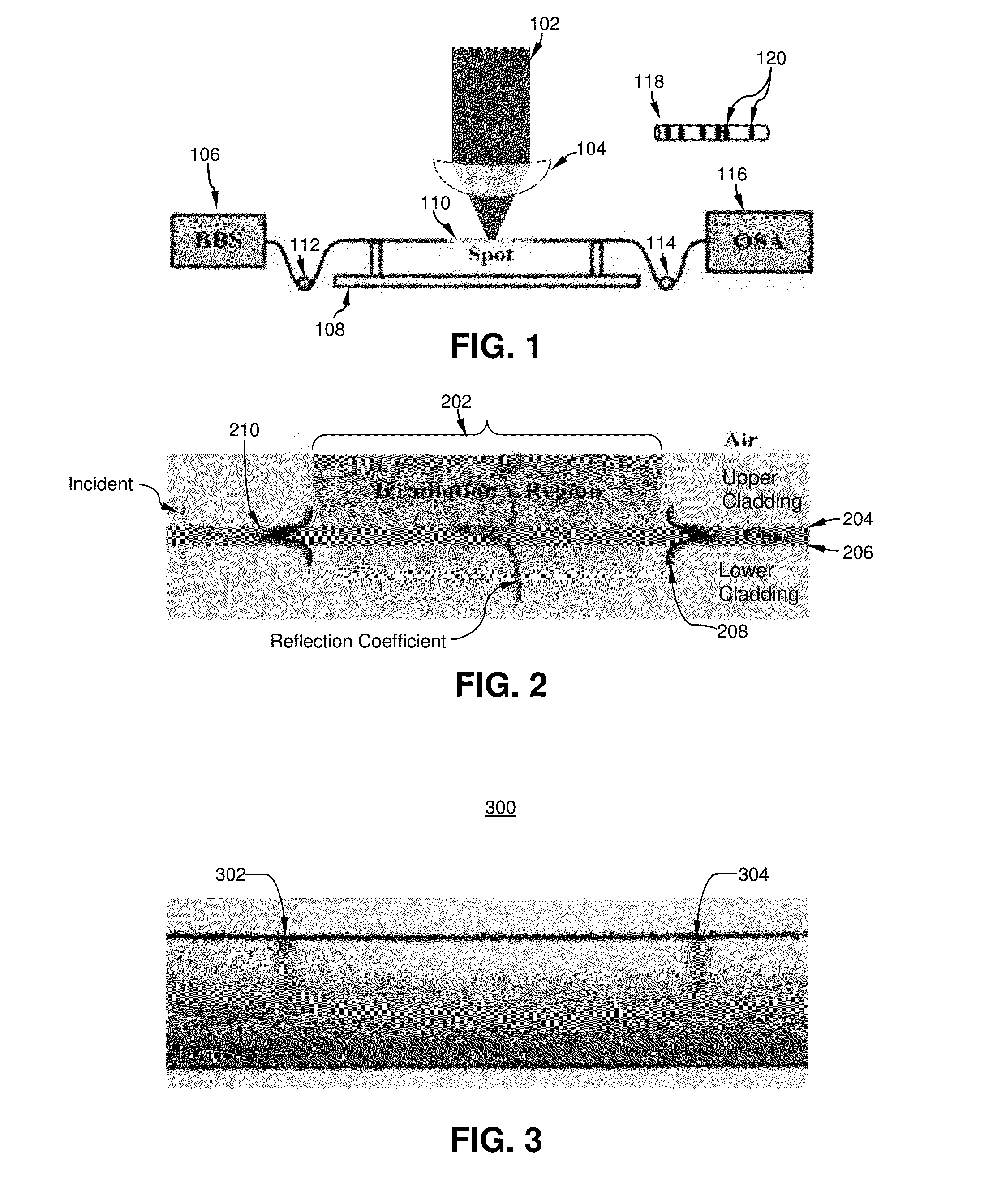
[0006]The foregoing needs are met, to a great extent, by the present invention wherein, according to a first broad aspect, the present invention provides a method comprising inducing random distributed feedback within one or more fiber sections of a fiber ring laser to thereby produce single-mode lasing with a reduced frequency jitter and a reduced relative intensity noise in the fiber ring laser. Inducing the random distributed feedback within the one or more fiber sections comprises modulating a refractive index at plurality of random points along the one or more fiber sections of the fiber ring laser.
[0007]According to a second broad aspect, the present invention provides an apparatus comprising a fiber ring laser comprising one or more random distributed feedback fiber sections configured to produce a single mode lasing with reduced frequency jitter and intensity noise in the fiber ring laser, wherein the one or more random distributed feedback fiber sections each comprise a plurality of randomly spaced refractive index modulation regions.

Problems solved by technology

In many conventional single-mode random distributed feedback (RDFB) laser systems the long length of a feedback fiber required for generation of random distributed feedback based on Rayleigh backscattering results in a high intensity noise and frequency instability thus degrading the performance of the RDFB laser.

Method used


Image

  • Frequency-stabilized random distributed feedback fiber ring laser with low intensity noise
  • Frequency-stabilized random distributed feedback fiber ring laser with low intensity noise
  • Frequency-stabilized random distributed feedback fiber ring laser with low intensity noise

Examples


Embodiment Construction

Definitions

[0022]Where the definition of terms departs from the commonly used meaning of the term, applicant intends to utilize the definitions provided below, unless specifically indicated.

[0023]For purposes of the present invention, it should be noted that the singular forms, “a,”“an” and “the,” include reference to the plural unless the context as herein presented clearly indicates otherwise.

[0024]For purposes of the present invention, directional terms such as “top,”“bottom,”“upper,”“lower,”“above,”“below,”“left,”“right,”“horizontal,”“vertical,”“up,”“down,” etc., are used merely for convenience in describing the various embodiments of the present invention. The embodiments of the present invention may be oriented in various ways. For example, the diagrams, apparatuses, etc., shown in the drawing figures may be flipped over, rotated by 90° in any direction, reversed, etc.

[0025]For purposes of the present invention, a value or property is “based” on a particular value, property, t...


PUM


Abstract

A method and apparatus for producing single mode random fiber ring laser by inducing random distributed feedback in a short section of the fiber ring to thereby enable single mode lasing while reducing frequency jitter and relative intensity noise. The random distributed feedback maybe achieved through deep refractive index modulation at a series of randomly distributed laser-irradiated points inscribed along the length of the induced random distributed feedback fiber. The laser-processed random distributed feedback fiber maybe incorporated into the fiber ring in conjunction with a variable optical attenuator and band pass optical filter for enhancing the single mode operation.

Description

[0001]This application claims benefit of priority to U.S. Provisional Patent Application No. 61 / 948,068, entitled, “Narrow linewidth low frequency noise Er-doped fiber ring laser based on femtosecond laser induced random feedback,” filed Mar. 5, 2014 which is incorporated herein by reference in its entirety.BACKGROUND[0002]1. Field of the Invention[0003]The present invention relates to random fiber lasers. More specifically, the present invention is directed to high performance single-mode fiber lasers.[0004]2. Related Art[0005]In many conventional single-mode random distributed feedback (RDFB) laser systems the long length of a feedback fiber required for generation of random distributed feedback based on Rayleigh backscattering results in a high intensity noise and frequency instability thus degrading the performance of the RDFB laser. It would be highly desirable to have a randomly distributed feedback feature for realizing narrow linewidth single-mode lasing without incurring ex...

Claims


Application Information

Patent Timeline
Patent Type & Authority Applications(United States)
IPC IPC(8): H01S3/067H01S3/0941H01S3/13H01S3/094
CPCH01S3/0675H01S3/06791H01S3/06716H01S3/1305H01S3/094003H01S3/0941H01S3/06712H01S2301/02H01S3/094042H01S3/10023
Inventor LI, YANGLU, PINGBAO, XIAOYIOU, ZHONGHUA
Owner UNIVERSITY OF OTTAWA
Why Eureka
Try Eureka