
System and method for stabilizing a laser output frequency

a laser and optical output technology, applied in the field of system and method for stabilizing the frequency of the optical output signal of the laser, can solve the problems of adverse effects, reducing or completely eliminating the frequency stability of the laser, and achieve the effect of reducing the frequency jitter of the laser and more accurate phase detection and measuremen

Inactive Publication Date: 2006-02-28
THE BOEING CO
View PDF6 Cites 3 Cited by
  • Summary
  • Abstract
  • Description
  • Claims
  • Application Information

AI Technical Summary

Benefits of technology

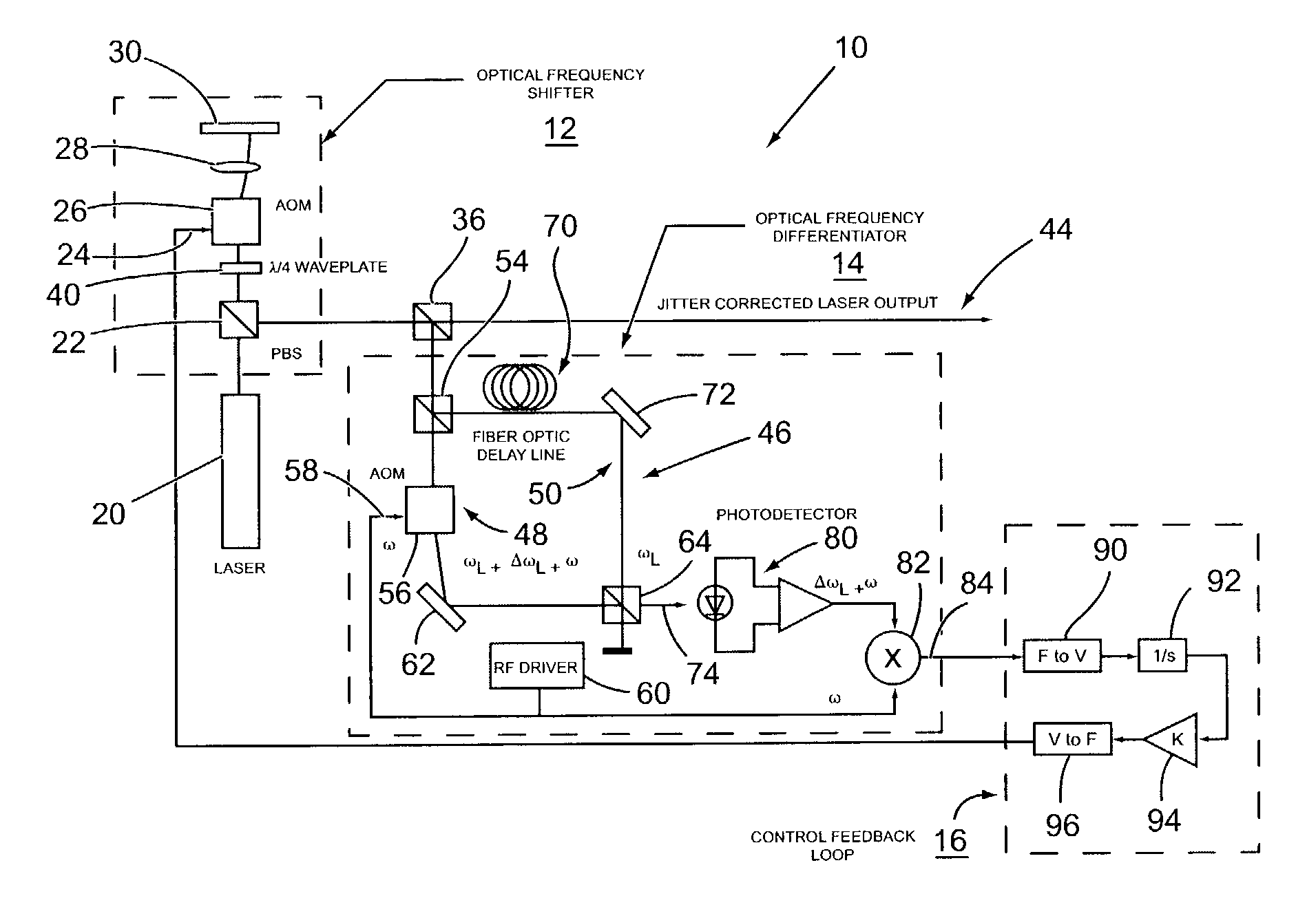
[0003]The present invention reduces the frequency jitter of a laser, allowing for more accurate phase detection and measurement even when the optical path lengths of the interferometer are very different. The system of the present invention is comprised of (1) a controllable optical frequency shifter, (2) an optical frequency differentiator, and (3) a control feedback loop. The controllable optical frequency shifter allows a corrective signal to be added to the optical frequency of a laser. Using the appropriate corrective signal, it is possible to compensate for drift in the laser frequency such that the laser output frequency remains substantially constant.
[0005]The control feedback loop processes the frequency drift error signal to generate a frequency correction signal. This frequency correction signal is inputted to the controllable optical frequency shifter to shift the optical frequency by an amount opposite to the detected drift. The action of the control feedback loop minimizes the amplitude of the error signal from the frequency differentiator, and therefore stabilizes the optical output frequency of the laser.

Problems solved by technology

The amplitude of the phase jitter increases with increasing frequency jitter and increasing difference in the optical path lengths of the two beams The frequency stability of a laser can be adversely affected by thermal effects, vibration, and other influences that are difficult and expensive to reduce or completely eliminate.

Method used


Image

  • System and method for stabilizing a laser output frequency
  • System and method for stabilizing a laser output frequency
  • System and method for stabilizing a laser output frequency

Examples


Embodiment Construction

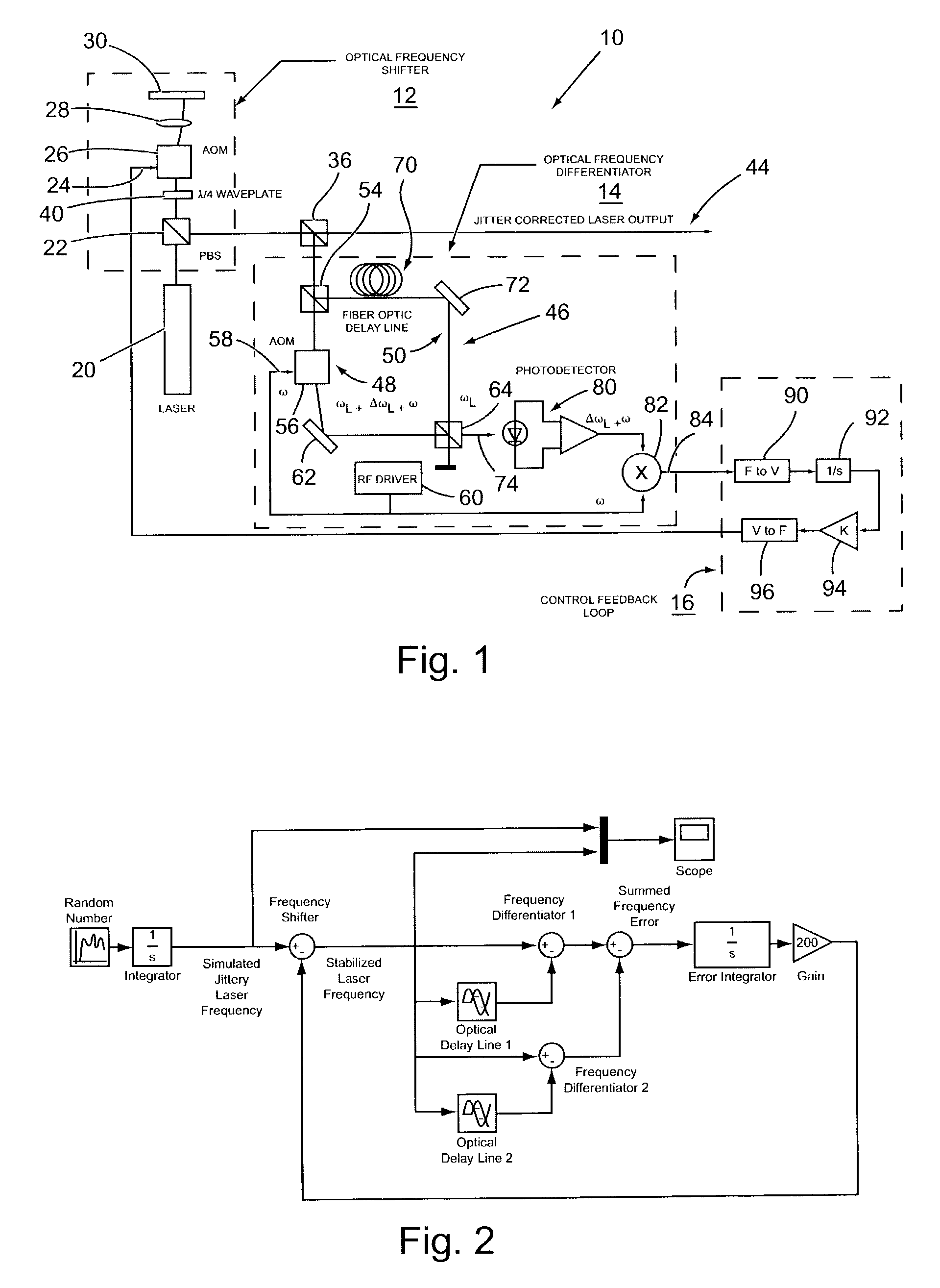
[0010]With reference to FIG. 1, there is shown a heterodyne implementation of a system 10 of the present invention for stabilizing the frequency of a laser optical output signal. Generally, the system 10 comprises an optical frequency shifter 12, an optical frequency differentiator 14, and a control feedback loop 16.

[0011]The optical frequency shifter 12 functions to allow a correction signal to be added to the optical output signal of the laser to cause a shift in the laser output frequency to compensate for drift in a laser output frequency, thereby producing a substantially constant laser output. In this described embodiment, the optical frequency shifter 12 is implemented by a single acousto-optic modulator (AOM) using a polarizing beam splitter to pass the laser output beam through the AOM twice. Thus, in accordance with this embodiment, the optical output signal of a linearly polarized laser 20 passes through a polarizing beam splitter (PBS) 22, then through a quarter wave wav...


PUM


Abstract

A system and method for stabilizing the frequency of the optical output signal of a laser wherein the laser output signal is interfered with at least one time delayed version of said signal to produce an optical interference signal having a frequency shift proportional to the rate of optical frequency change of the laser. The interference signal is processed to produce a frequency correction signal representing the frequency drift of the laser output signal. The laser output signal is combined with the frequency correction signal to stabilize the frequency of the laser output signal.

Description

BACKGROUND OF THE INVENTION[0001]The present invention is directed to a system and method for stabilizing the frequency of the optical output signal of a laser, and more specifically for stabilizing the output signal by applying a corrective signal to the output signal without modification to the internal laser cavity.[0002]The frequency stability of lasers allows for their application in interferometry. In interferometry, the laser beam is split into two paths and then recombined. A difference in the optical path length between the two paths produces a differential phase shift between the two recombined beams. This phase shift modulates the intensity of the recombined beams where the maximum intensity is achieved when both beams are in phase, and minimum intensity occurs when the two beams are 180° out of phase. Information from the interferometer requires accurate measurement of this intensity to determine the differential phase. If the laser output is not stable in frequency, whe...

Claims


Application Information

Patent Timeline
Patent Type & Authority Patents(United States)
IPC IPC(8): H01S3/13H01S3/137H01S3/139
CPCH01S3/137H01S3/1398
Inventor MUENTER, STEVEN E.
Owner THE BOEING CO
Learn More