Water-pollutant separation device, water-pollutant separation and filtration device, ornamental fish tank water-pollutant separation and filtration system, and high density cultivation water-pollutant separation, filtration and oxygen aeration system
a technology of water-pollutant separation and filtration device, which is applied in the direction of filtration separation, moving filter element filter, separation process, etc., can solve the problems of reducing the water flow rate and filtration effect, reducing the efficiency of filtration, and reducing the time-consuming work of washing filtration materials, etc., to achieve easy disassembly and cleaning, and the effect of discharging pollutan
- Summary
- Abstract
- Description
- Claims
- Application Information
AI Technical Summary
Benefits of technology
Problems solved by technology
Method used
Image
Examples
third embodiment
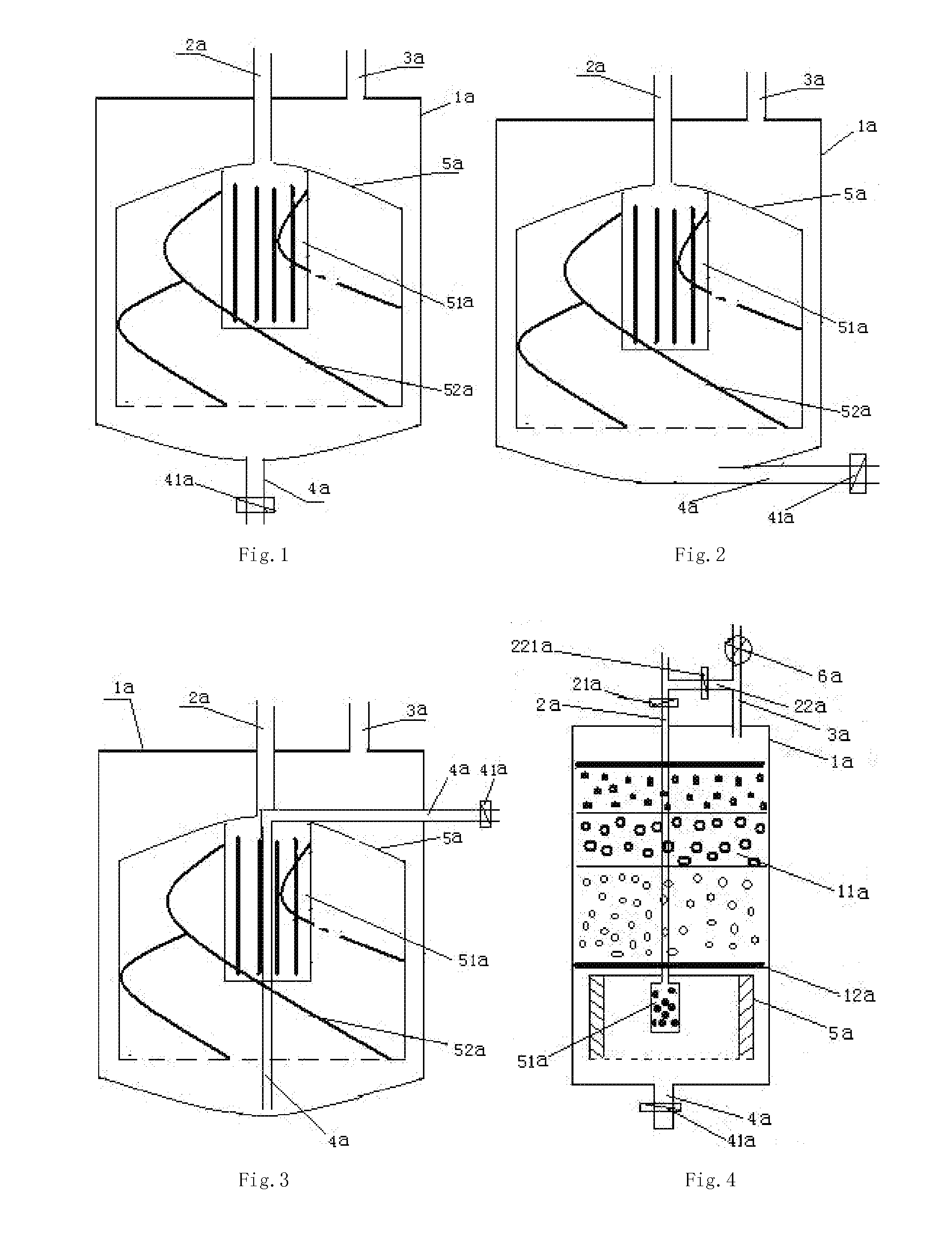
[0054]FIG. 2 and FIG. 3 are schematic views of a second and the water-pollutant separation device according to the present invention, which have a similar structure with the embodiment in FIG. 1. The difference is that the pollutant discharge pipe 4a for discharging pollutant at the bottom of the tank 1a is extending along the horizontal direction below the bottom of the tank 1a to reduce the total product height (as shown in FIG. 2), or is extending along the horizontal direction inside the tank 1a (as shown in FIG. 3).
[0055]When the device in a normal working state, the pollutant discharge pipe valve 41a is turned off and dirty water goes into the spoiler 51a through the water inlet pipe 2a inside the separation structure 5a. With the shunting function of the slots, the cycling water loses impact force and becomes smooth, and then starts whirling in the same direction under the function of the spiral leaves 52a, gathering most particles pollutant within a central area of the botto...
second embodiment
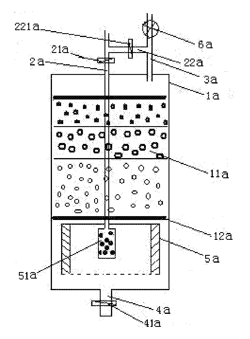
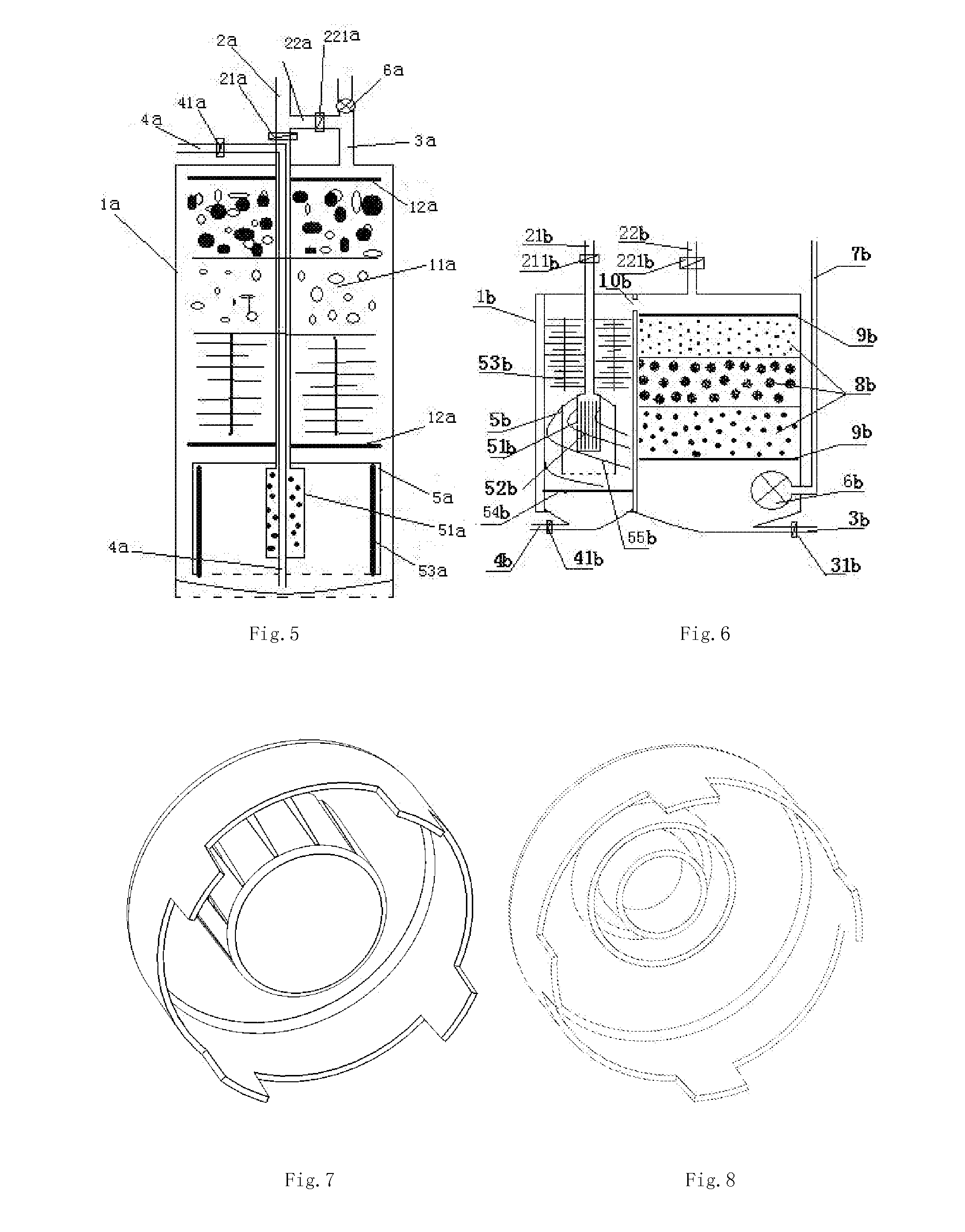
[0060]FIG. 5 is a schematic view of the water-pollutant separation and filtration device according to the present invention, which has a similar structure with the embodiment in FIG. 4. The difference is that the pollutant discharge pipe 4a for discharging pollutant at the bottom of the tank 1a is extending along the horizontal direction inside the tank 1a from bottom to top and then stretch out to reduce the total product height. Still, low density filtration materials 52a, such as brushes made into circle plate or the like, are arranged on the inner side-wall of the separation structure 5b to enhance the filtration effect of weak flow.
[0061]FIG. 6 is a schematic view of one embodiment of the ornamental fish tank water-pollutant separation and filtration system according to the present invention. The inner cavity of the tank 1b is divided by clapboard into the bottom-water filtration area on the left side and the upper-water filtration area on the right side communicating with each...
PUM
| Property | Measurement | Unit |
|---|---|---|
| dimensions | aaaaa | aaaaa |
| density | aaaaa | aaaaa |
| water flow rate | aaaaa | aaaaa |
Abstract
Description
Claims
Application Information
 - R&D
- Intellectual Property
- Life Sciences
- Materials
- Tech Scout
- Unparalleled Data Quality
- Higher Quality Content
- 60% Fewer Hallucinations
Browse by: Latest US Patents, China's latest patents, Technical Efficacy Thesaurus, Application Domain, Technology Topic, Popular Technical Reports.
© 2025 PatSnap. All rights reserved.Legal|Privacy policy|Modern Slavery Act Transparency Statement|Sitemap|About US| Contact US: help@patsnap.com


