Parameter distribution mapping in a gas turbine engine

a technology of gas turbine engine and distribution mapping, which is applied in the direction of machines/engines, instruments, heat measurement, etc., can solve the problems of controller changing the operating condition of the engine, destroying the components of the combustion engine, and affecting the operation of the engin

Active Publication Date: 2015-09-17
SIEMENS ENERGY INC
View PDF5 Cites 41 Cited by
  • Summary
  • Abstract
  • Description
  • Claims
  • Application Information

AI Technical Summary

Problems solved by technology

Thus, flame flashback and / or other combustion anomalies may cause undesirable damage and possibly even destruction of combustion engine components, such that repair or replacement of such components may become necessary.
For example, a controller may monitor a measured turbine exhaust temperature, and a measured change in temperature at the exhaust may result in the controller changing an operating condition of the engine.
In other known types of control arrangements discrete pitot-static or multi hole pressure probes are utilized to determine gas flow velocity at specific locations, but grid arrays of such probes disrupt gas flow and introduce measurement errors.
Due to such gas flow disruptions, grid arrays, when employed, have limited numbers of widely spaced probes, which provide relatively coarse gas flow velocity distribution and profile information.
However, these techniques are more complex than intrusive differential pressure or thermal anemometry instruments and require more specialized training to implement in monitoring systems.
Tunable Diode Laser Absorption Spectroscopy (TDLAS) instrumentation is used in some industrial power generation field applications, such as for temperature measurement in boilers but that instrumentation is extremely costly: approximately US $500,000 per system.

Method used


Image

  • Parameter distribution mapping in a gas turbine engine
  • Parameter distribution mapping in a gas turbine engine
  • Parameter distribution mapping in a gas turbine engine

Examples


Embodiment Construction

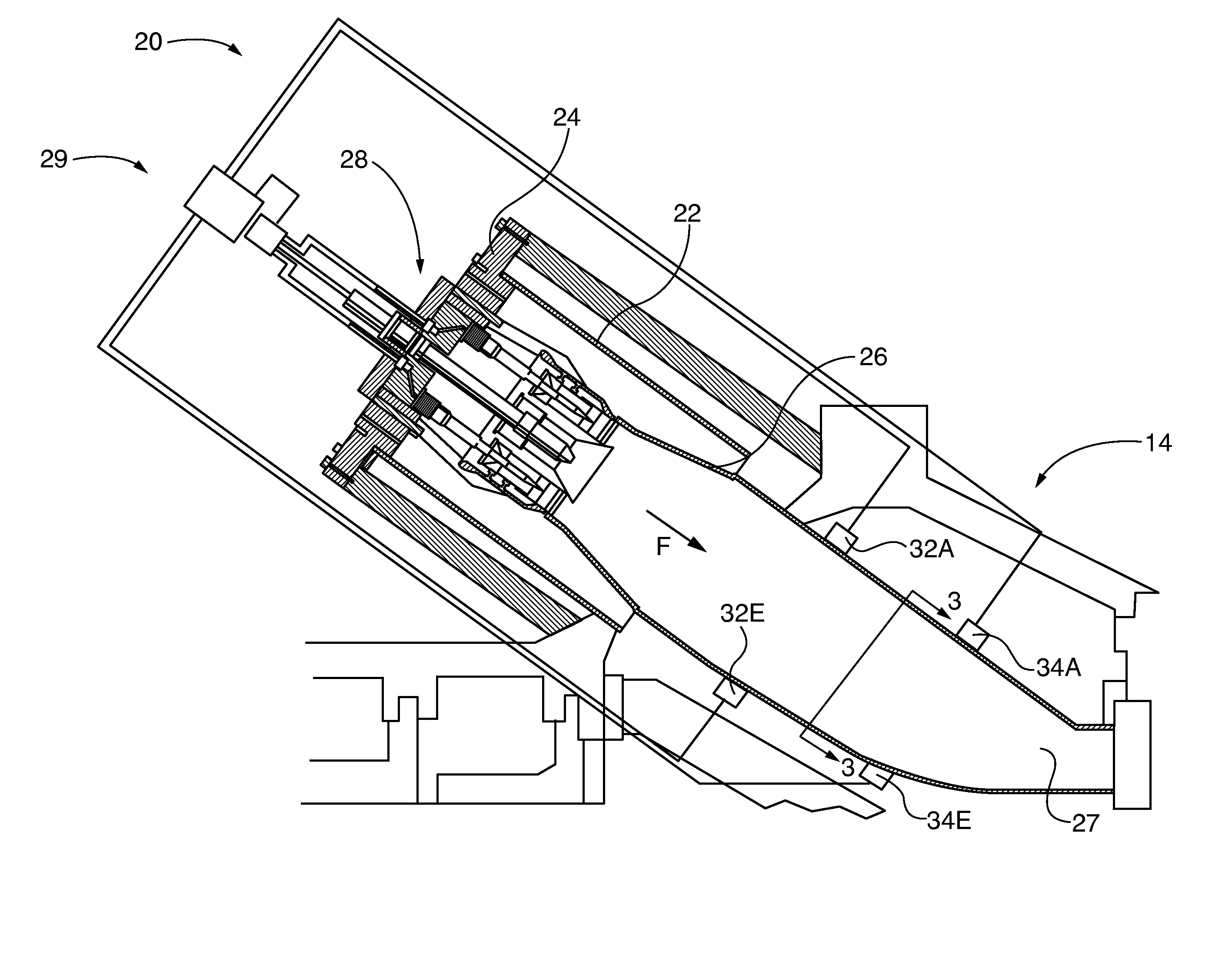
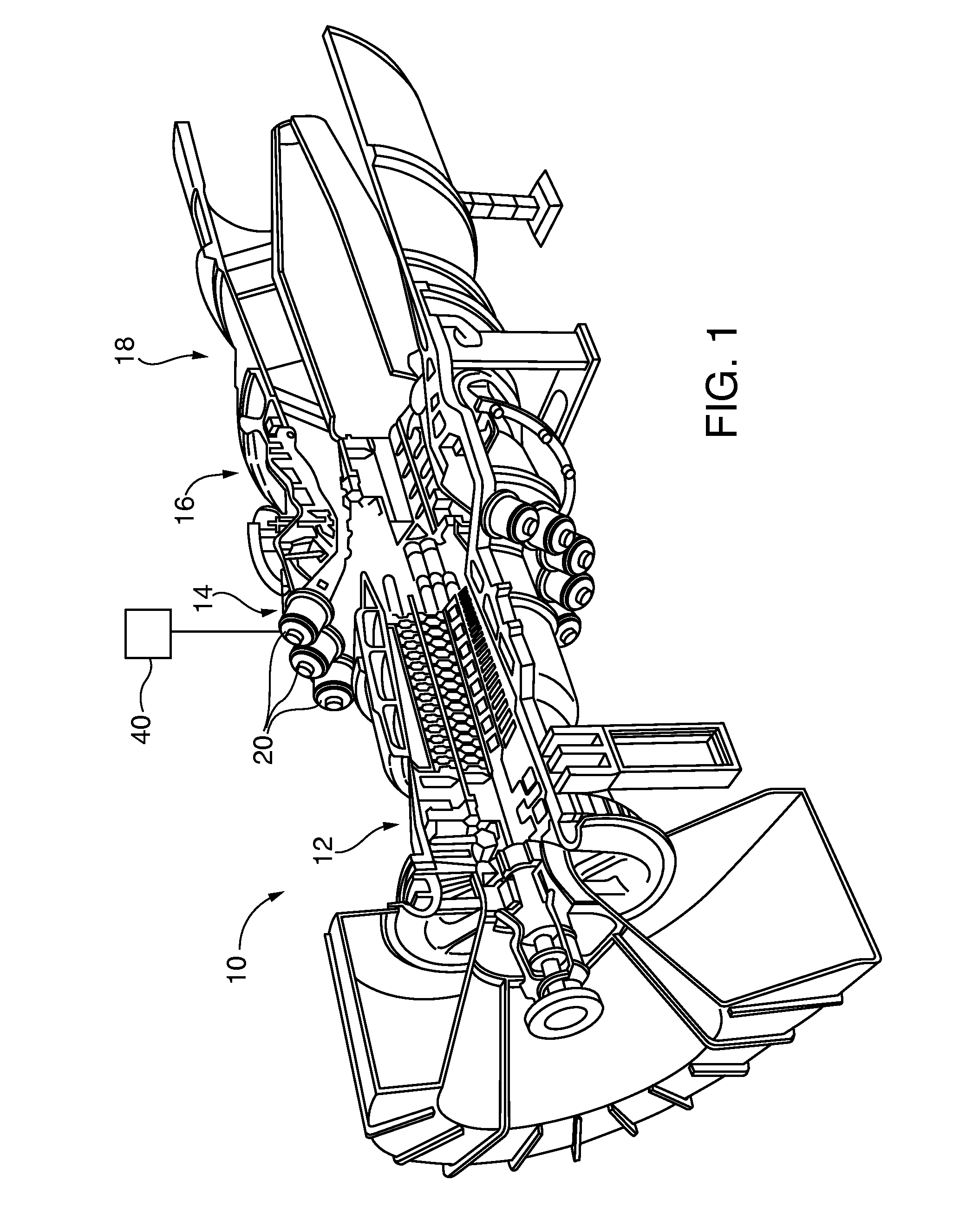
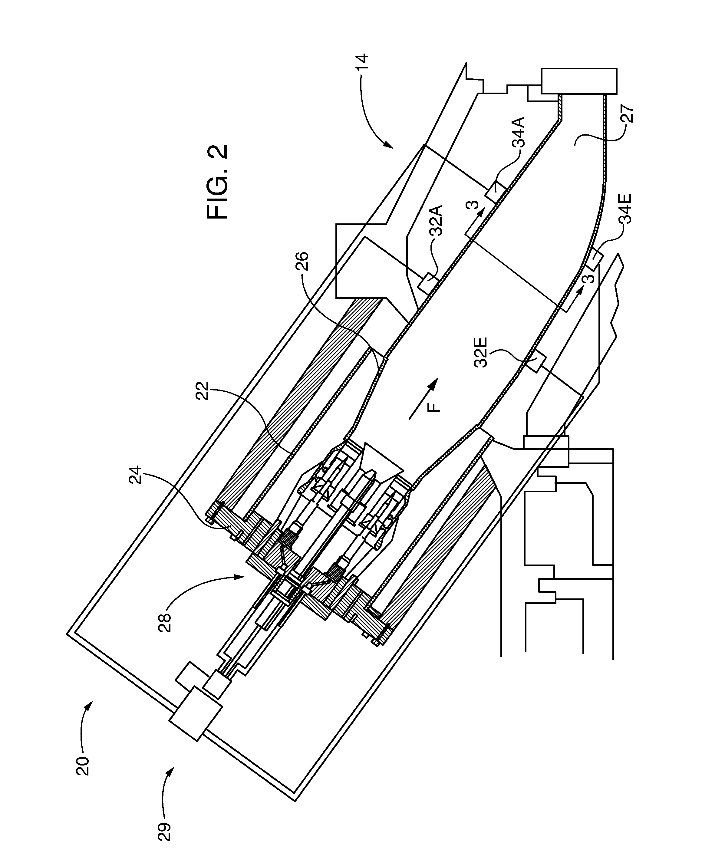
[0061]After considering the following description, those skilled in the art will clearly realize that the teachings of the invention can be readily utilized for active acoustic velocity and pyrometry-based gas flow velocity and temperature measurement. Embodiments of the invention are used for monitoring of gas turbine combustors, including industrial gas turbine (IGT) combustors by incorporating them into the combustion monitoring and control system by addition of an acoustic transmitter or acoustic transceiver that transmits sound waves through gas flow in a line-of-sight with a plurality of acoustic sensors, such as dynamic pressure sensors. For velocity measurement, sound transmission time-of-flight that is directed generally transversely through the gas flow path is measured by the controller and correlated with gas flow velocity along the line-of-sight. The gas flow velocity determination includes compensation for impact of the thermodynamically interrelated temperature, gas c...


PUM


Abstract

A profile map of parameter values in a region is determined based on average values along linear paths through the region. In one example, a temperature map of a region of a gas turbine engine is created based on time-of-flight measurements from acoustic transceiver pairs arranged circumferentially around the region. A speed of sound for each transceiver pair is determined based on the time-of-flight measurements. An average temperature along each path is estimated from the time of flight, and the profile map is computed from the average temperatures. The profile map may be computed using a polynomial approximation technique, a grid optimization technique or a basis function technique.

Description

CROSS-REFERENCE TO RELATED APPLICATIONS[0001]This application is a continuation in part of copending U.S. patent application entitled “Active Measurement of Gas Flow Velocity or Simultaneous Measurement of Velocity and Temperature, Including in Gas Turbine Combustors”, filed on Mar. 13, 2014, Ser. No. 14 / 207,803, which is incorporated herein by reference in its entirety and to which this application claims the benefit of priority. This application claims the benefit under 35 U.S.C. §119(e) of U.S. Provisional Patent Application No. 61 / 983,044 entitled “Temperature Distribution Mapping in a Gas Turbine Combustor”, filed on Apr. 23, 2014, which is incorporated herein by reference in its entirety and to which this application claims the benefit of priority.[0002]This application incorporates by reference the following co-pending United States utility patent applications in their entirety as if fully set forth herein:[0003]“Nonintrusive Performance Measurement of a Gas Turbine Engine in...

Claims


Application Information

Patent Timeline
Patent Type & Authority Applications(United States)
IPC IPC(8): G01M15/14G01F1/66F02C9/50
CPCG01M15/14F05D2270/11G01F1/663F02C9/50G01K11/24G01K13/02G01F1/668G01K2213/00G01K13/024
Inventor DESILVA, UPUL P.CLAUSSEN, HEIKO
Owner SIEMENS ENERGY INC
Why Eureka
Try Eureka