Method and device for detecting ionising radiation using a pixelated photodetector

a technology of ionising radiation and detector, applied in the direction of measurement devices, radiation measurement, instruments, etc., can solve the problems of complex and costly detectors, inability to achieve significant resolution gains, and inability to accurately estimate the energy deposited by the photon

Active Publication Date: 2015-09-17
COMMISSARIAT A LENERGIE ATOMIQUE ET AUX ENERGIES ALTERNATIVES
View PDF2 Cites 12 Cited by
  • Summary
  • Abstract
  • Description
  • Claims
  • Application Information

AI Technical Summary

Problems solved by technology

The charge sharing phenomenon mentioned above does not however allow any significant gains in resolution to be achieved; neither does it allow the energy deposited by the photon to be estimated with precision.
Furthermore, it requires a very large number of amplifiers, ADC converters and processing circuits, leading to complex and costly detectors.
Furthermore, this results in difficulties in hybridisation of the detector in the circuit.
This method however has the drawback of using signals from pixels adjacent to the pixel affected at the moment when the signals are very small, with the result that they are usually drowned out by the noise.
A significant error in the coordinates of the point of interaction could therefore result from this.
The drawback of this method is again that it is very sensitive to noise, in particular when the interaction position is close to the centre of the affected pixel.
The result of this is that the amplitude peak may then be drowned by the noise, and that errors adversely affect the estimate of the interaction position.

Method used


Image

  • Method and device for detecting ionising radiation using a pixelated photodetector
  • Method and device for detecting ionising radiation using a pixelated photodetector
  • Method and device for detecting ionising radiation using a pixelated photodetector

Examples


first embodiment

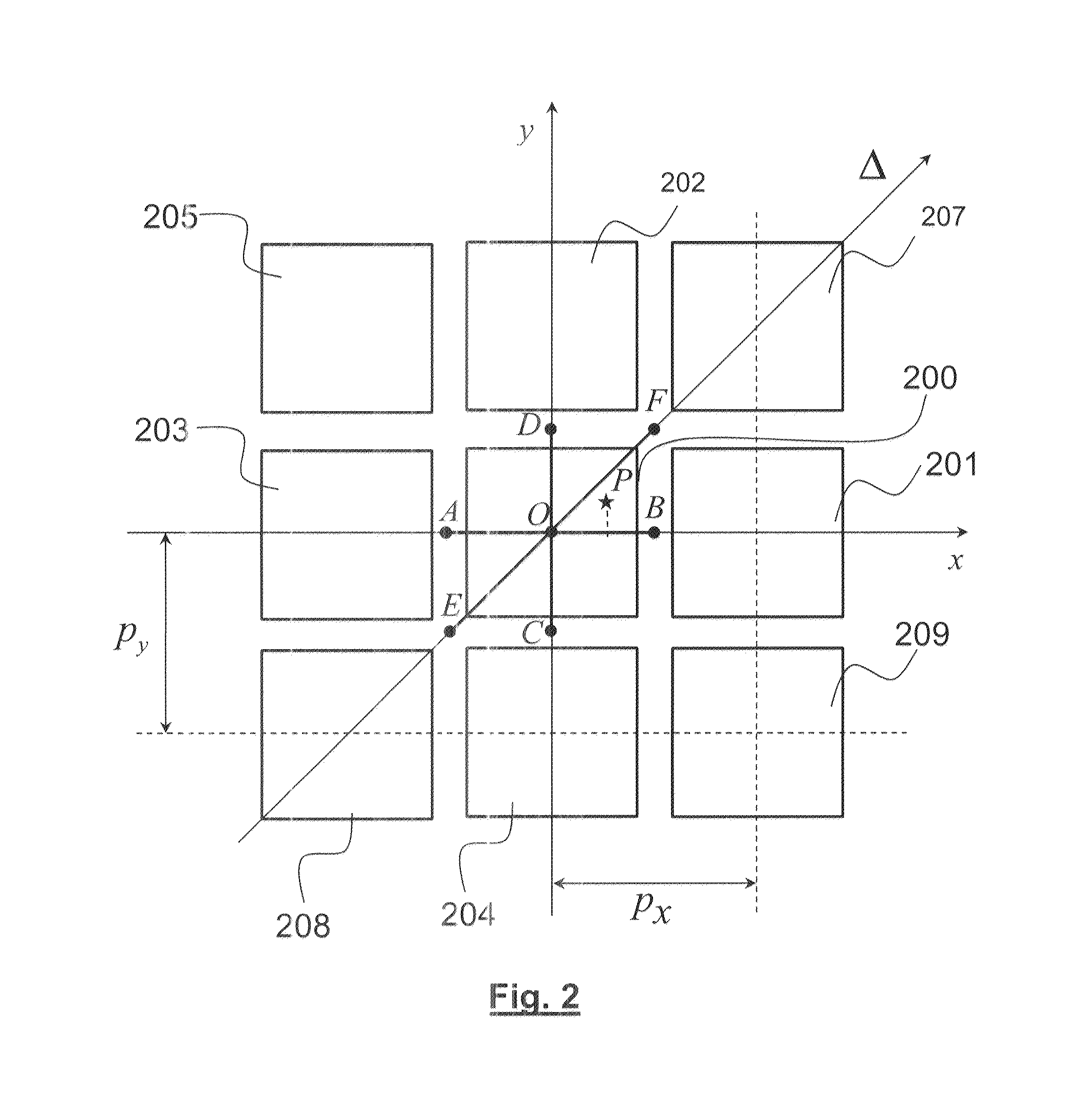
[0026] the coordinate, x, of the point of interaction is estimated using an estimate of the maximum likelihood, by jointly maximising the conditional probabilities p(MQ|xi), Q ∈V, where the xi are multiple discrete possible values of said coordinate, where the conditional probability functions p(MQ|xi) have been determined beforehand in a calibration or simulation phase.

[0027]The coordinate, x, of the point of interaction can then be estimated by means of:

x^=argmaxi(∏Q∈VP(MQxi))

[0028]According to a variant of the first embodiment, the coordinate, x, of the point of interaction is estimated using estimation of the maximum likelihood by jointly maximising the conditional probabilities p( MQ|xi), Q ∈V, where MQ is the deviation normalised by the energy E0 of the signal of the affected pixel and where the xi are multiple discrete possible values of the said coordinate, where the conditional probability functions p( MQ|xi) have been determined beforehand in a calibration or simulation ph...

second embodiment

[0032] the coordinate of the point of interaction is estimated by:

{circumflex over (x)}=U(Bx)

where Bx is the coordinate of the barycentre of the pixels of V weighted by their receptive deviations, MQ, and of the affected pixel, weighted by the amplitude of the signal of said affected pixel at the time of impact, and where U(Bx) is a function which renders uniform the distribution of Bx under uniform illumination of the detector, determined by calibration or simulation.

[0033]The function U(Bx) is advantageously determined by U(Bx)=p[F(Bx)−1 / 2] where p is the pixelation interval of the detector and F(Bx) is the distribution function of the barycentre Bx under uniform illumination of the detector.

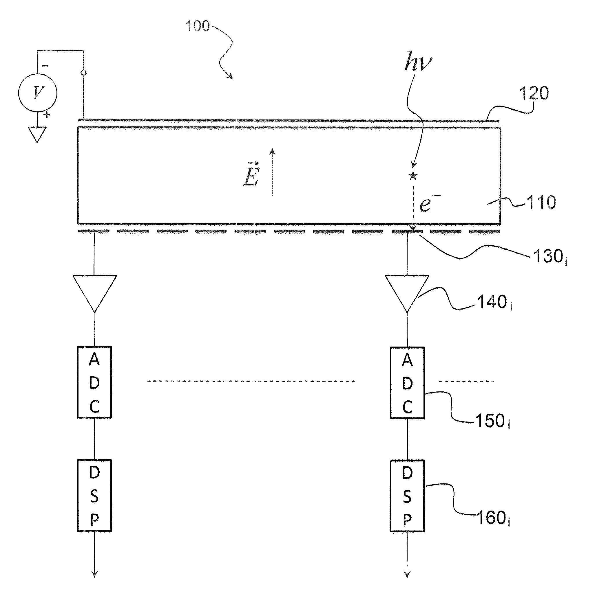
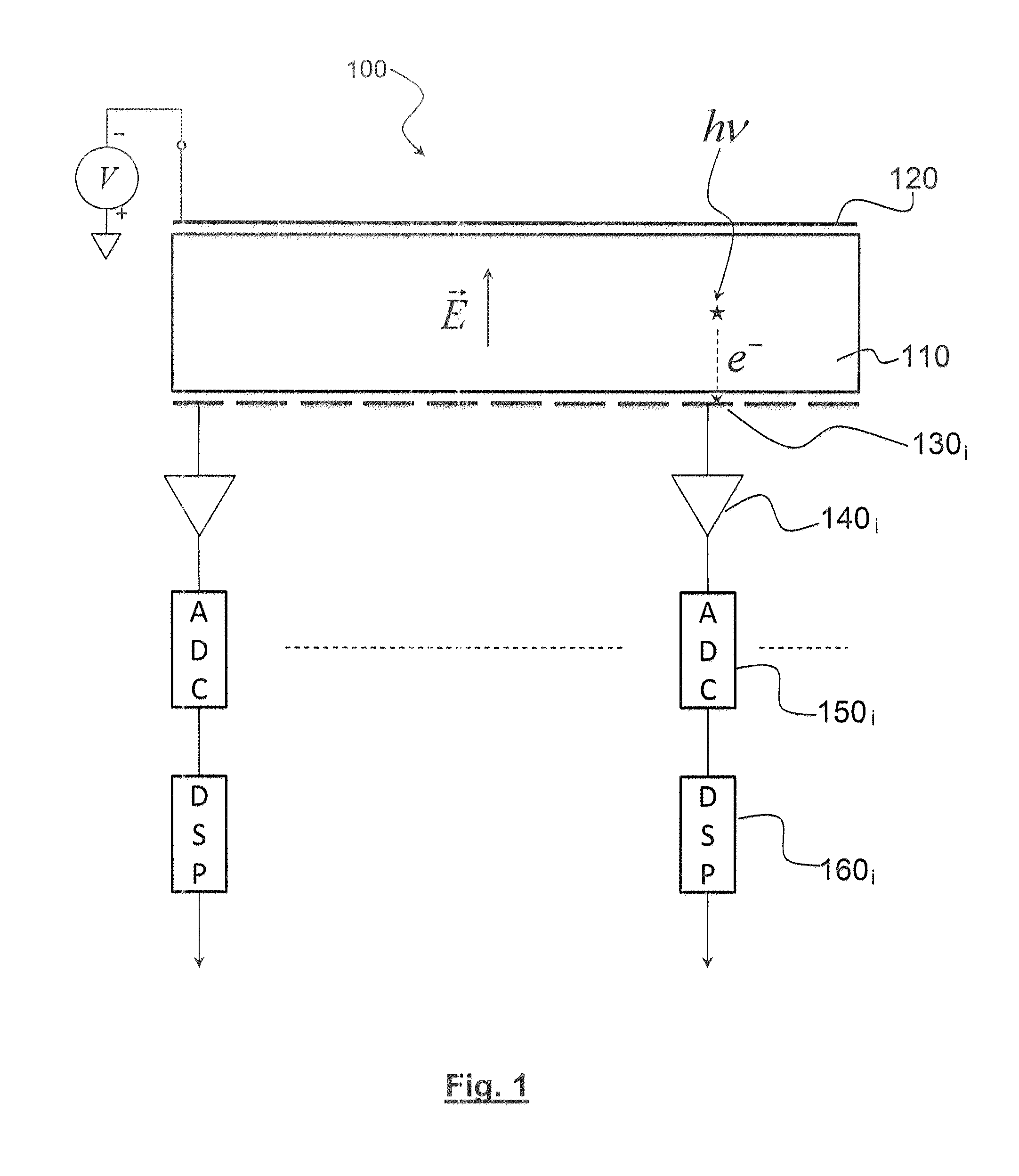
[0034]The invention also relates to an ionising radiation detector comprising a semi-conductor element which has a front side exposed to the ionising radiation covered with a first electrode, and a rear side covered with multiple elementary electrodes, known as pixels, where each pixel is asso...


PUM


Abstract

A method for detecting ionising radiation using a pixelated semi-conductor detector. When the radiation interacts with the detector, the affected pixel is determined, together with the instant of impact for this pixel. A first instant before and a second instant after the instant of impact are deduced from this. The deviations of the signals coming from an assembly of pixels adjacent to the affected point are then measured, with the deviations being measured between the first and second instants. The position of the point of interaction of the radiation with the semi-conductor is estimated from the deviations thus measured.

Description

TECHNICAL FIELD[0001]The invention relates in general terms to the field of ionising radiation detectors and that of methods for processing signals from such detectors.STATE OF THE PRIOR ART[0002]Semi-conductor detectors for ionising radiation such as, for example, X-ray or γ radiation, are well known in the prior art, particularly in the fields of medicine, of astronomy and non-destructive testing.[0003]When these detectors are used for imaging, they must be capable of allowing spatial discrimination of the incident photons.[0004]An ionising radiation detector structure commonly used for imaging is shown in FIG. 1.[0005]This detector 100 comprises a semi-conductor element 110 whose front side, exposed to the incident radiation is covered with a first electrode 120 and the rear side is covered with multiple second elementary electrodes 130i distributed in a one- or two-dimensional periodic arrangement. Thus, depending on the case, the second elementary electrodes can take form of st...

Claims


Application Information

Patent Timeline
Patent Type & Authority Applications(United States)
IPC IPC(8): G01T1/24G01T1/29
CPCG01T1/2914G01T1/24G01T1/2928
Inventor LUX, SILVEREMONTEMONT, GUILLAUME
Owner COMMISSARIAT A LENERGIE ATOMIQUE ET AUX ENERGIES ALTERNATIVES
Why Eureka
Try Eureka