
Multiple electrode lens arrangement and a method for inspecting an object

a multi-electrode lens and object technology, applied in the field of inspection/measurement techniques, can solve the problems of enlarge the diameter, limit the system resolution, unsatisfactory specimen charging, etc., and achieve the effect of increasing the symmetry of the electromagnetic field

Active Publication Date: 2007-06-19
APPL MATERIALS ISRAEL LTD
View PDF7 Cites 10 Cited by
  • Summary
  • Abstract
  • Description
  • Claims
  • Application Information

AI Technical Summary

Benefits of technology

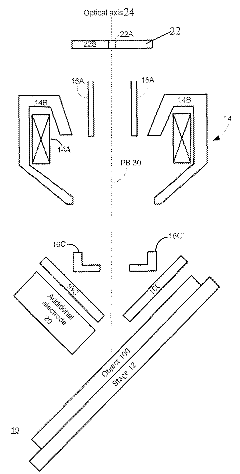
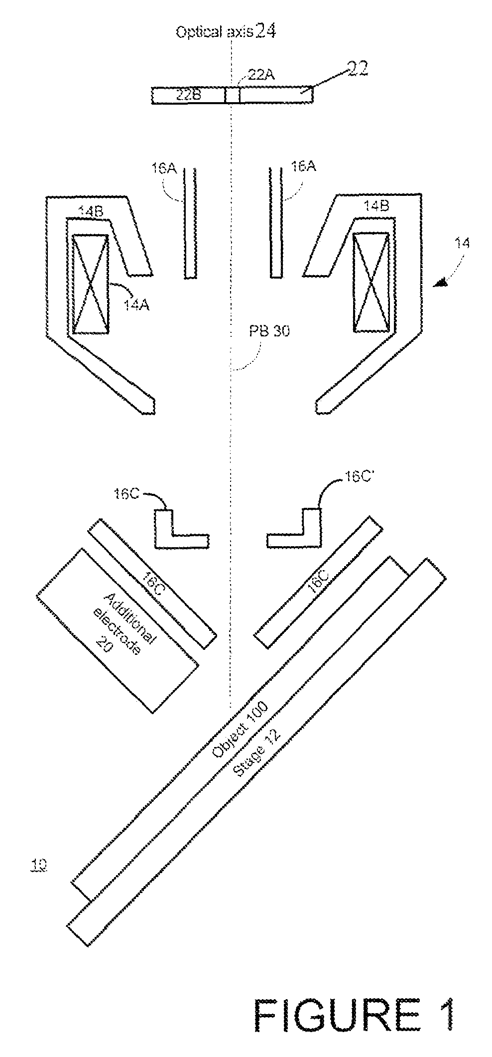
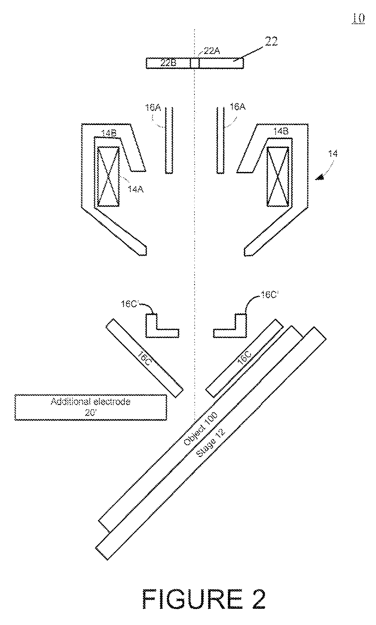
The patent describes an inspection system that uses a lens to direct a primary electron beam towards an object at a non-normal angle. The system also includes an additional electrode positioned outside the lens to increase the symmetry of the electromagnetic field at the interaction point between the electron beam and the object. The technical effect of this system is that it allows for more accurate and symmetrical inspection of objects using a primary electron beam.

Problems solved by technology

However, it has been observed that such a highly energized electron beam causes damage to resist structures and integrated circuits, and, in the case of dielectric specimens, causes undesirable charging of the specimen.
The operation with low primary beam energies (less than 1 keV), especially in large mechanical tilts (e.g., 45 degrees), limits the system resolution due to high chromatic aberration of the electrostatic part of the lens arrangement, namely, the distribution of the electrostatic field in the vicinity of the object.
This difference causes the enlargement of the diameter of the charged particle beam, and consequently, the reduction of resolution.

Method used


Image

  • Multiple electrode lens arrangement and a method for inspecting an object
  • Multiple electrode lens arrangement and a method for inspecting an object
  • Multiple electrode lens arrangement and a method for inspecting an object

Examples


Embodiment Construction

[0020]There is a need in the art to facilitate the monitoring of objects with a charged particle beam, by providing a novel lens arrangement for use in a charged particle beam column. Here, the term “monitoring” signifies at least one of the inspection and measurement techniques.

[0021]The term “primary beam” used herein (being also referred to as “primary charged particle beam” or “primary electron beam”) signifies a charged particle beam, which is formed by charged particles generated by a source (cathode) of these particles, and which is to be directed to an object to release charged particles forming a “secondary beam” (also referred to as “secondary charged particle beam” or secondary electron beam), which is to be detected.

[0022]The present invention is aimed at solving a problem of improving the resolution in a DR-SEM column, especially for low primary beam energies (less than 1 keV), for operation with large angles of primary beam incidence (e.g., 45 degrees) by using one or ...


PUM


Abstract

A inspection system includes: a lens arrangement adapted to generate a substantially symmetrical electrostatic field about an optical axis and to direct a primary electron beam towards an object that is oriented in relation to the optical axis at a non-normal angle; and at least on additional electrode, positioned outside the lens arrangement such as to increase symmetry of an electromagnetic field in the vicinity of an interaction point between the primary electron beam and the object. A method for inspecting an object includes: passing a primary electron beam, along an optical axis, through a substantially symmetrical electrostatic field defined within an electron lens arrangement; and propagating the primary electron beam from the lens arrangement towards an interaction point with an object that is oriented in relation to the optical axis at a non-normal angle, while maintaining, by at least one additional electrode positioned outside the lens arrangement, a substantially symmetrical electrical field in a vicinity of the interaction point.

Description

FIELD OF THE INVENTION[0001]The present invention is in the field of inspection / measurement techniques of the kind utilizing irradiation of an object by a focused beam of electrically charged particles, such as electrons, positrons, or ions, and relates to an lens arrangement for use in a charged particle beam column.BACKGROUND OF THE INVENTION[0002]Charged particle beam columns are typically employed in scanning electron microscopy (SEM), which is a known technique widely used in the manufacture of semiconductor devices, being utilized in CD metrology tools, the so-called CD-SEM (Critical Dimension Scanning Electron Microscope) and defect review SEM (DR-SEM). In an SEM, the region of an object to be examined is two-dimensionally scanned by means of a focused primary beam of electrically charged particles, usually electrons. Irradiation of the object with the primary electron beam releases secondary (and / or backscattered) electrons. The secondary electrons are released at that side ...

Claims


Application Information

Patent Timeline
Patent Type & Authority Patents(United States)
IPC IPC(8): G03B27/54G03B27/42
CPCG03B27/42G03B27/54
Inventor PETROV, IGORSHEMESH, DROR
Owner APPL MATERIALS ISRAEL LTD
Learn More