
Tethersonde system and observation method thereby

a technology of tethersonde and observation method, which is applied in the field of tethersonde system and observation method thereby, can solve the problems of increasing the risk of accidents, worse environmental pollution, and difficulty in using tethersonde, and achieve the effect of reducing the speed of falling

Inactive Publication Date: 2015-09-17
ELECTRONICS & TELECOMM RES INST
View PDF7 Cites 6 Cited by
  • Summary
  • Abstract
  • Description
  • Claims
  • Application Information

AI Technical Summary

Benefits of technology

The tethersonde system includes a device that slows down the radiosonde when it falls from the balloon. This is done using a parachute that is connected to the radiosonde. The technical effect of this is that it helps to prevent damage to the radiosonde during the measurement process.

Problems solved by technology

However, as the balloon ascends, it expands and eventually bursts, and then it falls to the ground with the radiosonde.
However, as weight of the device lifted up through the atmosphere increase, it may not be suitable for the low and middle atmospheric observation, may make environment pollution worse when it is not recovered due to atmospheric conditions, and may increase risks of accidents.
However, since unlike the radiosonde, the tethersonde tethered by a connection line cannot move along the wind, it requires additional anemoscope and anemometer to observe wind.
In addition, it may be difficult to use the tethersonde when the wind is strong since it is tethered, and to measure weather at altitudes higher than the middle layer due to heavier weight and higher volume than the radiosonde.
However, when wind is strong, observation may be difficult due to the tension-meter tethered by a connection line.
In addition, when wind force changes, the balloon may keep moving and a part of the wind force may be consumed for the kinetic energy.
Thus, it may cause errors in wind speed which is calculated using the string tension.

Method used


Image

  • Tethersonde system and observation method thereby
  • Tethersonde system and observation method thereby
  • Tethersonde system and observation method thereby

Examples


Embodiment Construction

[0033]While the present invention has been described with reference to particular embodiments, it is to be appreciated that various changes and modifications may be made by those skilled in the art without departing from the spirit and scope of the present invention, as defined by the appended claims and their equivalents.

[0034]Throughout the description of the present invention, when describing a certain technology is determined to evade the point of the present invention, the pertinent detailed description will be omitted. In addition, the numbers used in the description may be used to describe various components and are used only to distinguish one component from another.

[0035]When one element is described as being “connected” or “accessed” to another element, it shall be construed as being connected or accessed to the other element directly but also as possibly having another element in between.

[0036]Hereinafter, certain embodiments of the present invention will be described wit...


PUM


Abstract

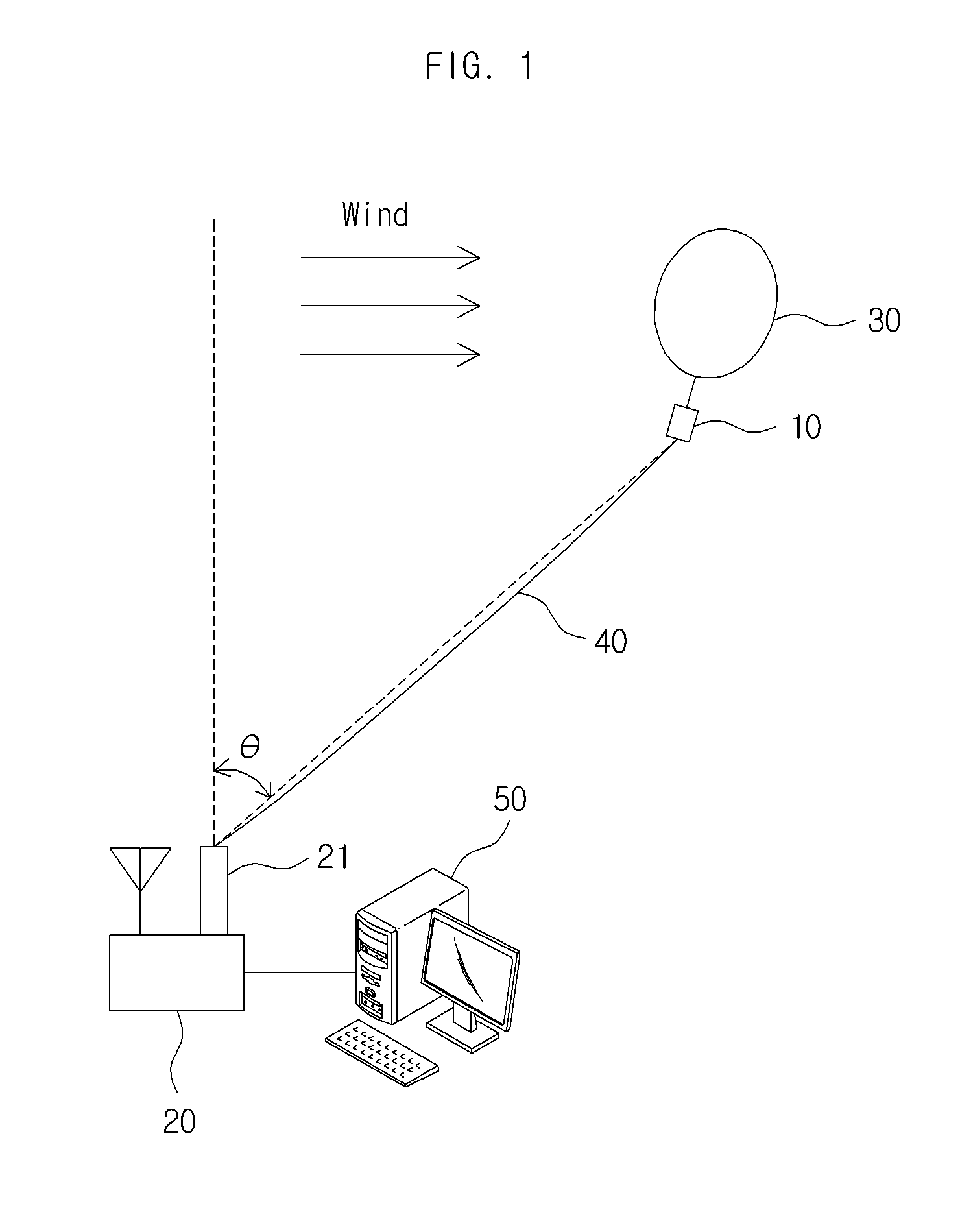
The present invention provides a tethersonde system and an observation method thereby. The tethersonde system comprises a balloon, a radiosonde observing weather while being carried aloft by the balloon and transmitting weather data including position information, a ground receiver receiving and analyzing the weather data and determining wind direction and speed of the atmospheric layer using the position information, and a connection line connecting the ground receiver and the radiosonde and being wound or unwound to control an observation point of the radiosonde.

Description

CROSS REFERENCE TO RELATED APPLICATION[0001]This application claims priority to and the benefit of Korean Patent Application No. 10-2014-0029093, filed on Mar. 12, 2014, entitled “Tethersonde system and observation method thereby”, which is hereby incorporated by reference in its entirety into this application.BACKGROUND OF THE INVENTION[0002]1. Technical Field[0003]The present invention relates to a tethersonde system and an observation method thereby.[0004]2. Description of the Related Art[0005]A radiosonde for upper air observation is carried aloft by the balloon and measures and transmits weather data to a ground receiver as it ascends. The radiosonde is equipped with sensors such as a thermometer, a hygrometer, and a barometer, a GPS receiver, and a wireless transmitter. It periodically measures weather information as it ascends and wirelessly transmits the result. The ground receiver receives weather data from the radiosonde and analyzes and stores the data. The balloon to lif...

Claims


Application Information

Patent Timeline
Patent Type & Authority Applications(United States)
IPC IPC(8): G01W1/08
CPCG01W1/08
Inventor NAM, HONG-SOON
Owner ELECTRONICS & TELECOMM RES INST
Learn More