
Array antennas having a plurality of directional beams

a technology of array antenna and directional beam, which is applied in the field of directional antennas, can solve the problems of low utilization rate of wireless bandwidth provided by the antenna, interference of the directional antenna, and large lens size,

Active Publication Date: 2015-09-17
UBIQUITI INC
View PDF4 Cites 176 Cited by
  • Summary
  • Abstract
  • Description
  • Claims
  • Application Information

AI Technical Summary

Benefits of technology

The patent relates to a new type of lens called lacunated lens, which is smaller and more efficient than traditional Rotman lenses used in optical systems. The smaller size of the lacunated lens allows for better performance in a smaller package. The increased path lengths through the body of the lens in the lacunated lens result in improved performance at a lower cost. Overall, this technology provides a more compact and high-performing optical solution for various applications.

Problems solved by technology

One challenge is how to increase the coverage of an AP to cover a large area with a few APs, while providing a user with the desired performance from the Wi-Fi network.
Because the antenna operates in a specific direction, communication by the directional antenna faces interference only from devices operating in its directional radiation.
Furthermore, end device in the coverage of a respective antenna usually contend among each other for airtime with the AP (i.e., transmission time between the AP and an end device), leading to a low-utilization of the wireless bandwidth provided by the antenna.
Unfortunately, such lenses must be relatively large and expensive, particularly in the RF frequency range (e.g., between 2 GHz and 50 GHz).
Although various improvements in Rotman lenses have been proposed, such improvements typically reduce the efficacy of the lens, and require somewhat expensive and complicated arrangements of features, including multiple dielectric materials.
Unfortunately, this form of transmission can be inefficient and noisy.

Method used


Image

  • Array antennas having a plurality of directional beams
  • Array antennas having a plurality of directional beams
  • Array antennas having a plurality of directional beams

Examples


Embodiment Construction

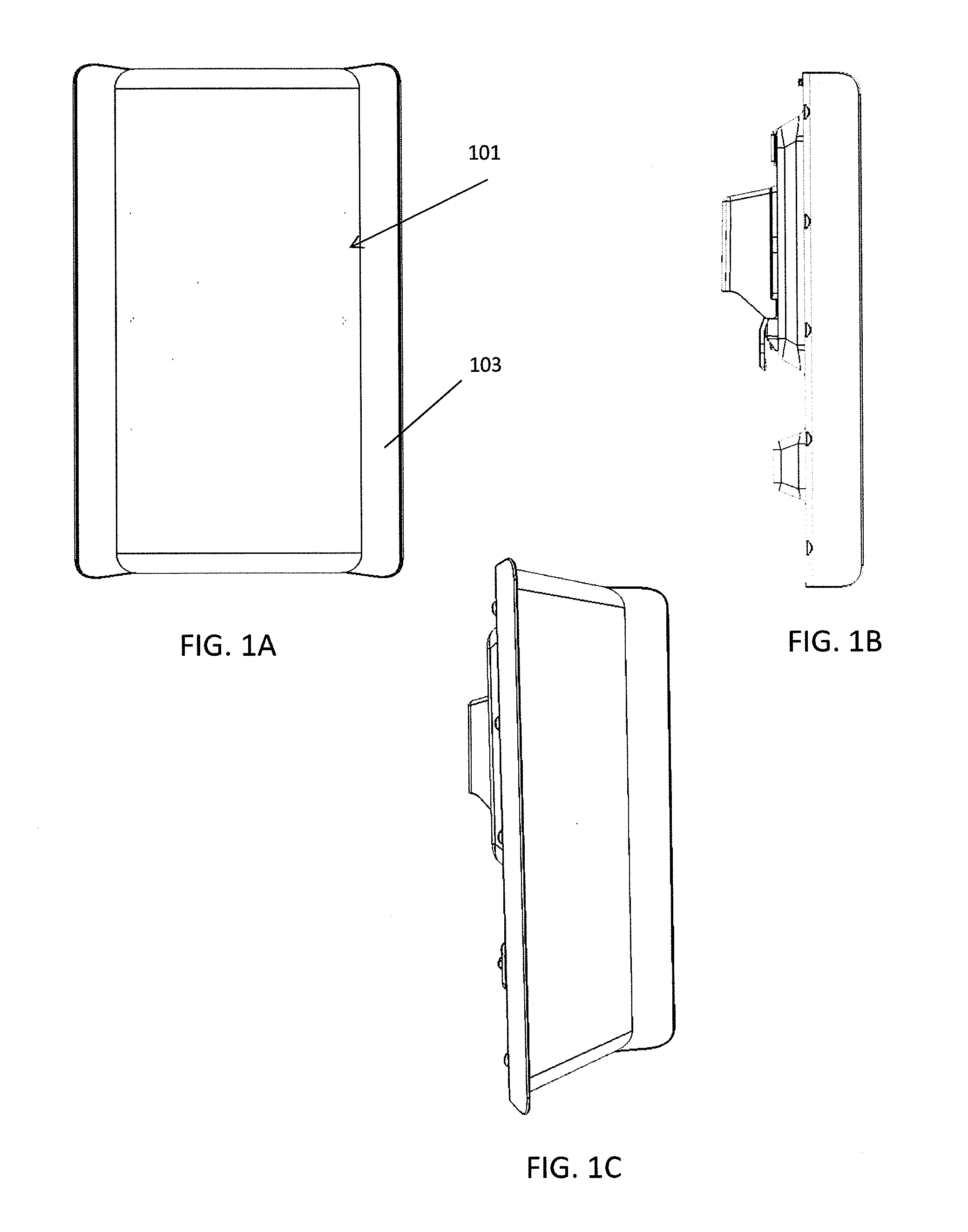
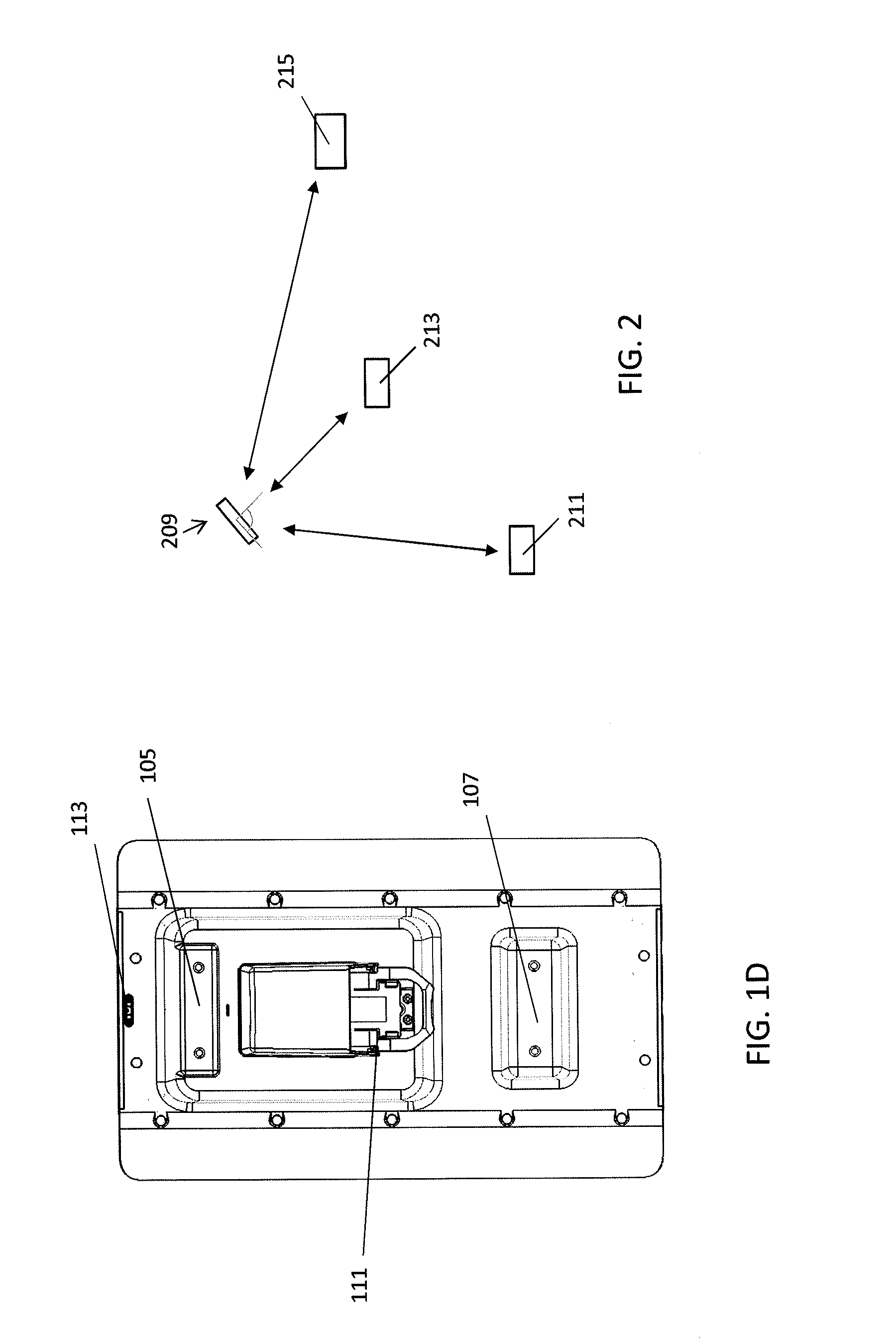
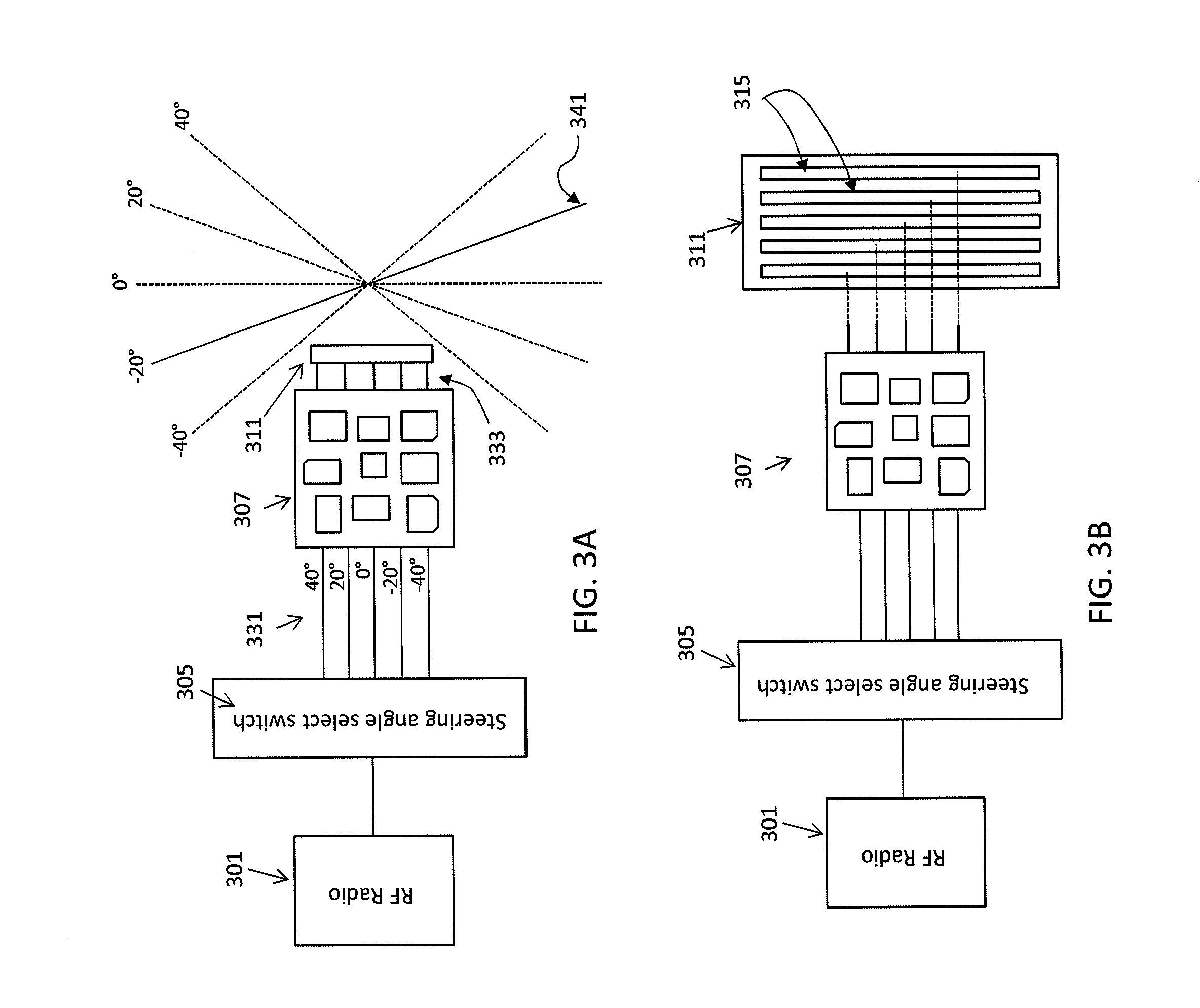
[0121]Phased array antennas are described herein, including phased array antennas that include a compact, electronic lens for steering (beamforming) the antenna. Features of the array antennas, and of systems including such antennas, are described in greater detail below, and may include: compact, electronic lenses (e.g., lacunated lenses) for steering a phased array antenna, phased array antennas incorporating such compact electronic lenses, phased array antennas adapted for use with a removable, self-contained RF radio (transceiver) device, methods and devices for identifying the type of antenna (including the type of phased array antenna) to which a removable, self-contained RF radio is connected, methods and device for controlling a phased array antenna by a removable, self-contained RF radio, and arrangements of antenna (emitting) elements within a phased array antenna. Also described herein are systems and methods of operating an access point using an antenna array, which may ...


PUM


Abstract

Multi-directional antenna apparatuses, which may include phased array antennas and / or arrays of multiple antennas, and methods for operating these directional antennas. In particular, described herein are apparatuses configured to operate as an access point (AP) for communicating with one or more station devices by assigning a particular directional beam to each access point, and communicating with each station device using the assigned directional beam at least part of the time. Methods and apparatuses configured to optimize the assignment of one or more directional beam and for communicating between different station devices using assigned directional beams are described. Also described are methods of connecting a radio device to an antenna by connecting a USB connector on the radio device to a USB connector on an antenna and identifying the antenna based on a voltage of the ground pin on the antenna's USB connector.

Description

CROSS REFERENCE TO RELATED APPLICATIONS[0001]This patent application claims priority to U.S. Provisional Patent Application No. 62 / 019,321, filed Jun. 30, 2014, and titled “PHASED ARRAY ANTENNAS;” and U.S. Provisional Patent Application No. 61 / 954,244, filed Mar. 17, 2014, and titled “MANAGING AN ARRAY OF ANTENNAE OF AN ACCESS POINT”. Each of these patent applications is herein incorporated by reference in its entirety.INCORPORATION BY REFERENCE[0002]All publications and patent applications mentioned in this specification are herein incorporated by reference in their entirety to the same extent as if each individual publication or patent application was specifically and individually indicated to be incorporated by reference.FIELD[0003]In general, described herein are directional antennas including phased array antennas and arrays of multiple antennas, and methods for operating the directional antennas. Also described herein are compact lacunated lenses that may be used for beamformi...

Claims


Application Information

Patent Timeline
Patent Type & Authority Applications(United States)
IPC IPC(8): H01Q3/24H01Q1/12H01Q21/00H01Q3/36
CPCH01Q3/24H01Q21/00H01Q1/12H01Q3/36H04B7/0639H04B7/0695H01Q25/008H01Q1/1228H01Q21/0031H04W16/28H01Q13/206H01Q3/46H01Q15/08H04B7/0617H04W84/12H04W88/08
Inventor SANFORD, JOHN R.DAYANANDAN, SRIRAMPONNAMPALAM, VISHJABBAZ, GONZALO P.PERA, ROBERT J.
Owner UBIQUITI INC
Learn More