Object information acquiring apparatus and breast examination apparatus
a technology of object information and acquisition apparatus, which is applied in the field of object information acquisition apparatus and to the breast examination apparatus, can solve the problems of difficult to accurately acquire acoustic images of the same segment, from the same direction, and achieve the effect of accurate acoustic images
- Summary
- Abstract
- Description
- Claims
- Application Information
AI Technical Summary
Benefits of technology
Problems solved by technology
Method used
Image
Examples
embodiment 1
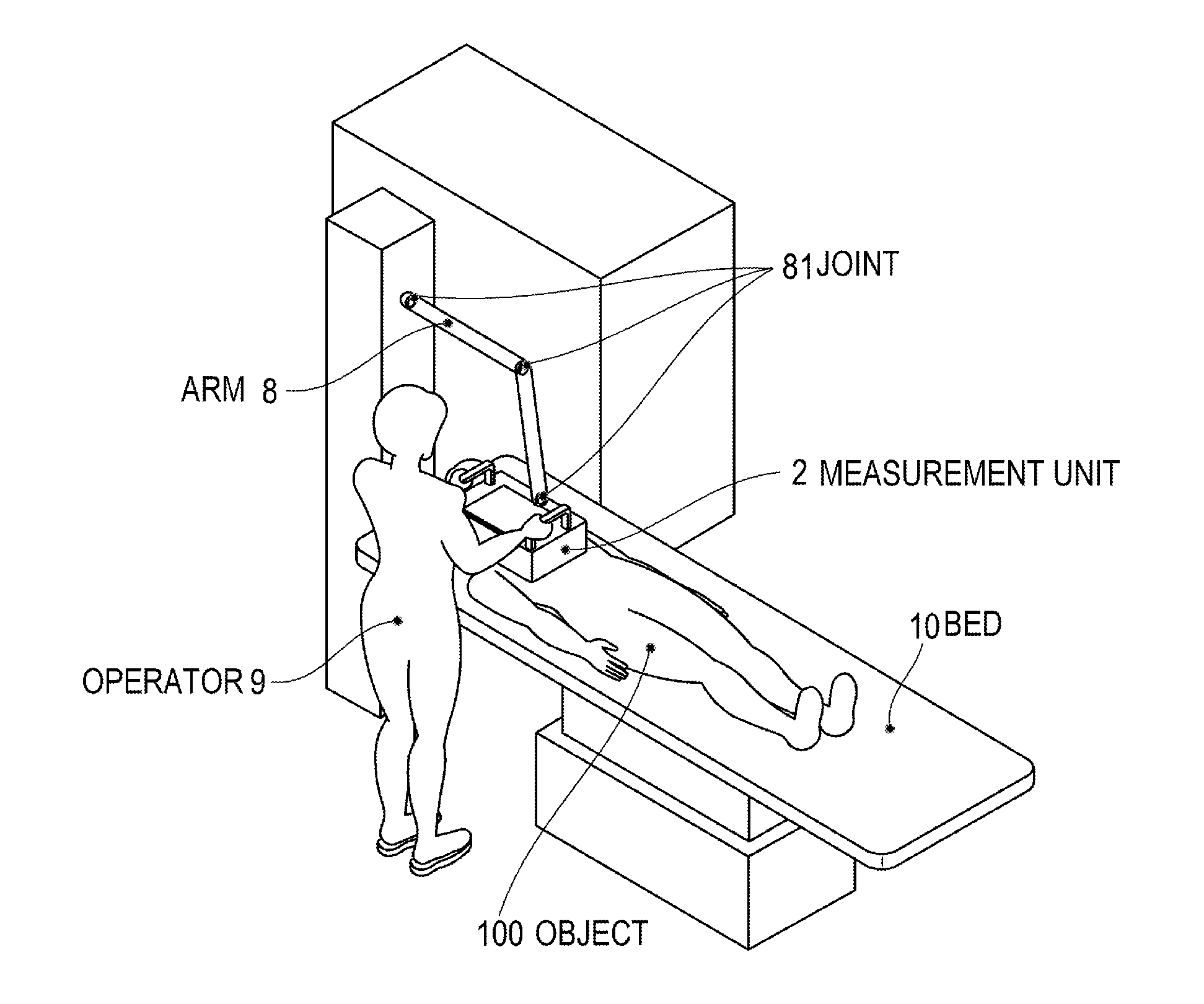
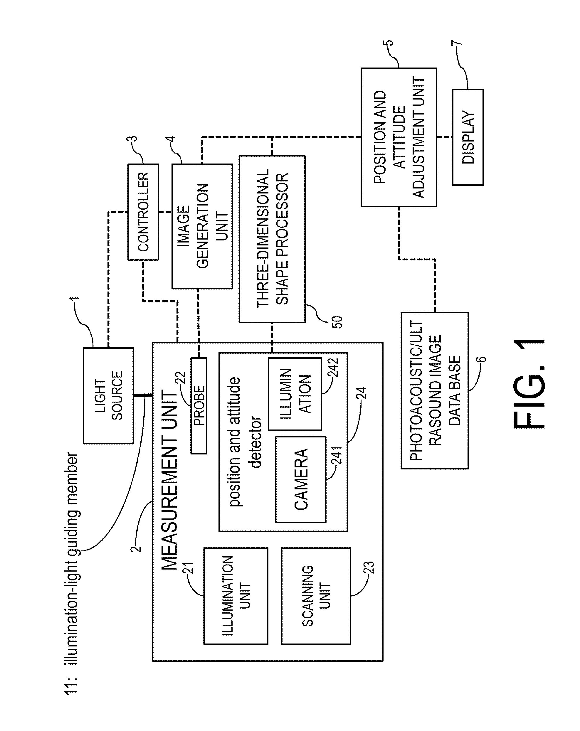
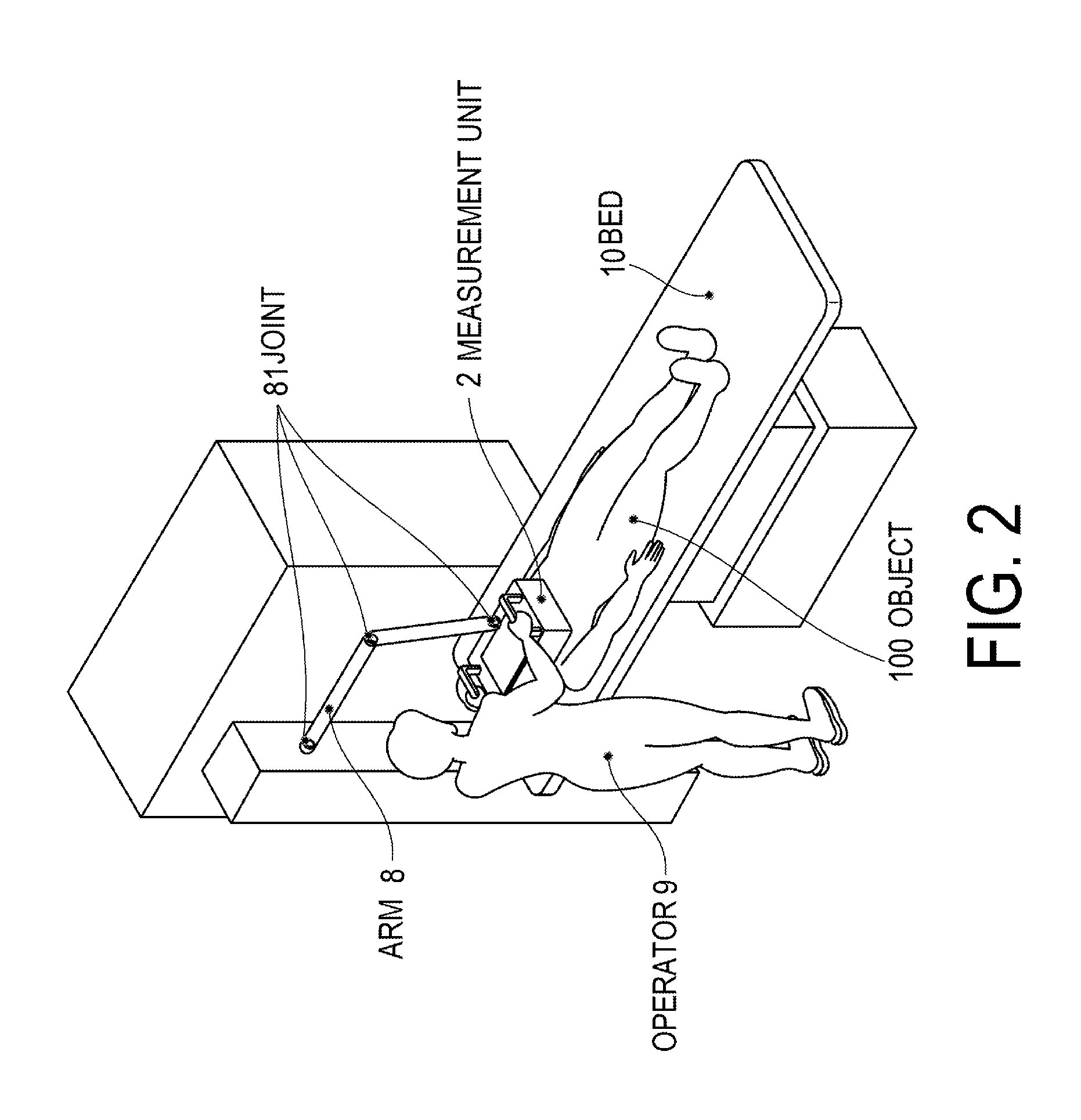
[0037]An acoustic measurement apparatus of the present invention will be explained next with reference to FIG. 1. In an acoustic measurement apparatus, illumination light generated in a light source 1 is guided to a measurement unit 2 using illumination-light guiding member 11. Preferably, the position and attitude of the measurement unit 2 can be modified in accordance with the position and posture of a subject. Such a configuration enables imaging at attitudes where little load is exerted on the subject. To achieve this, the illumination-light guiding member 11 is configured such that a light-guiding path, for instance an optical fiber or the like, can be modified flexibly in accordance with the measurement position.
[0038]The measurement unit 2 comprises an illumination unit 21, a probe 22, a scanning unit 23 and a position and attitude detector 24. Illumination light that is guided to the measurement unit 2 by the illumination-light guiding member 11 is supplied to the illuminati...
embodiment 2
[0072]FIG. 8 is a perspective view diagram of a measurement unit of a second embodiment of the acoustic diagnostic apparatus of the present invention. FIG. 8A is a perspective view diagram, FIG. 8B is a bottom-view diagram, and FIG. 8C is an A-A cross-sectional diagram. The measurement unit 2 of the present embodiment comprises the illumination unit 21, the probe 22, the scanning unit 23 and the position and attitude detector 24, as in Embodiment 1. The position and attitude detector 24 of the present embodiment has the cameras 241 outside the light-shielding cover 253. The position and attitude detector 24 of the present embodiment further has, inside the light-shielding cover 253, a transmission surface imaging camera 245 that captures the image of the left and right nipple points of the object 100, via the transmission surface 252. The transmission surface imaging camera 245 detects the positions of the left and right nipple points.
[0073]The position and attitude detector 24 of t...
embodiment 3
[0081]The display of the present embodiment will be explained with reference to FIG. 10. As in the case of Embodiment 1, photoacoustic images and ultrasound images acquired by the operator over a plurality of measurements are displayed, side by side, on the display. In Embodiment 3, moreover, there are displayed also a landmark 74 that denotes the position of an anatomical landmark, and coordinate axes 75 that denote the direction of a three-dimensional image in the subject coordinate system, on each three-dimensional photoacoustic image and ultrasound image. The landmark 74 is at least a mark that denotes the position of either one of the left and right nipple points illustrated in FIG. 4, and is displayed on the three-dimensional photoacoustic image or ultrasound image in such a manner that the landmark 74 is readily recognized by the operator and the subject. The coordinate axes 75 represent directions of respective axes in such a manner that the operator and the subject can reco...
PUM
 Abstract
Description
Claims
Application Information
 - R&D
- Intellectual Property
- Life Sciences
- Materials
- Tech Scout
- Unparalleled Data Quality
- Higher Quality Content
- 60% Fewer Hallucinations
Browse by: Latest US Patents, China's latest patents, Technical Efficacy Thesaurus, Application Domain, Technology Topic, Popular Technical Reports.
© 2025 PatSnap. All rights reserved.Legal|Privacy policy|Modern Slavery Act Transparency Statement|Sitemap|About US| Contact US: help@patsnap.com


