

Saturation-enhanced, low-concentration vaporized hydrogen peroxide decontamination method
- Summary
- Abstract
- Description
- Claims
- Application Information
AI Technical Summary
Benefits of technology
Problems solved by technology
Method used
Image

Examples
Embodiment Construction
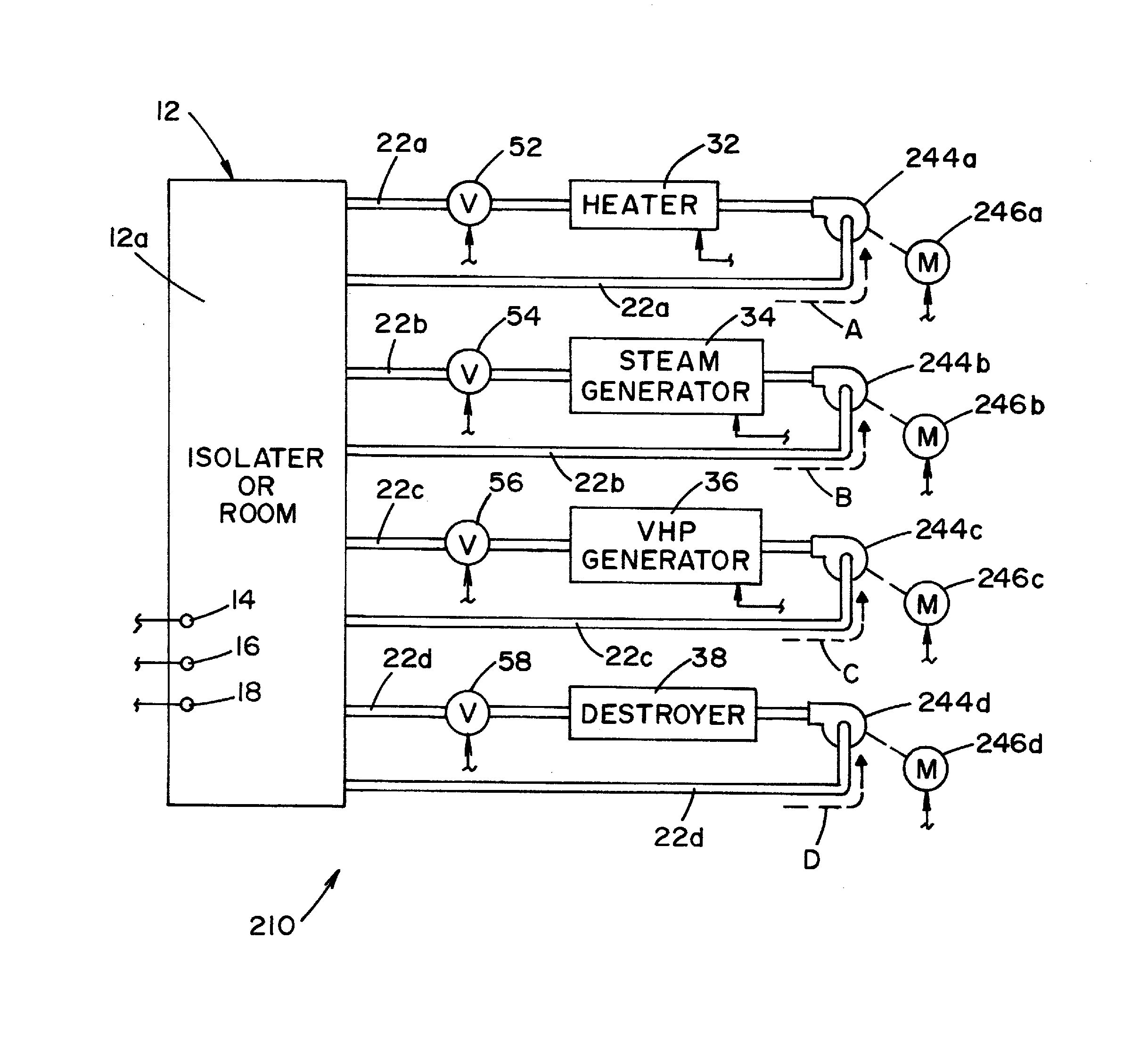
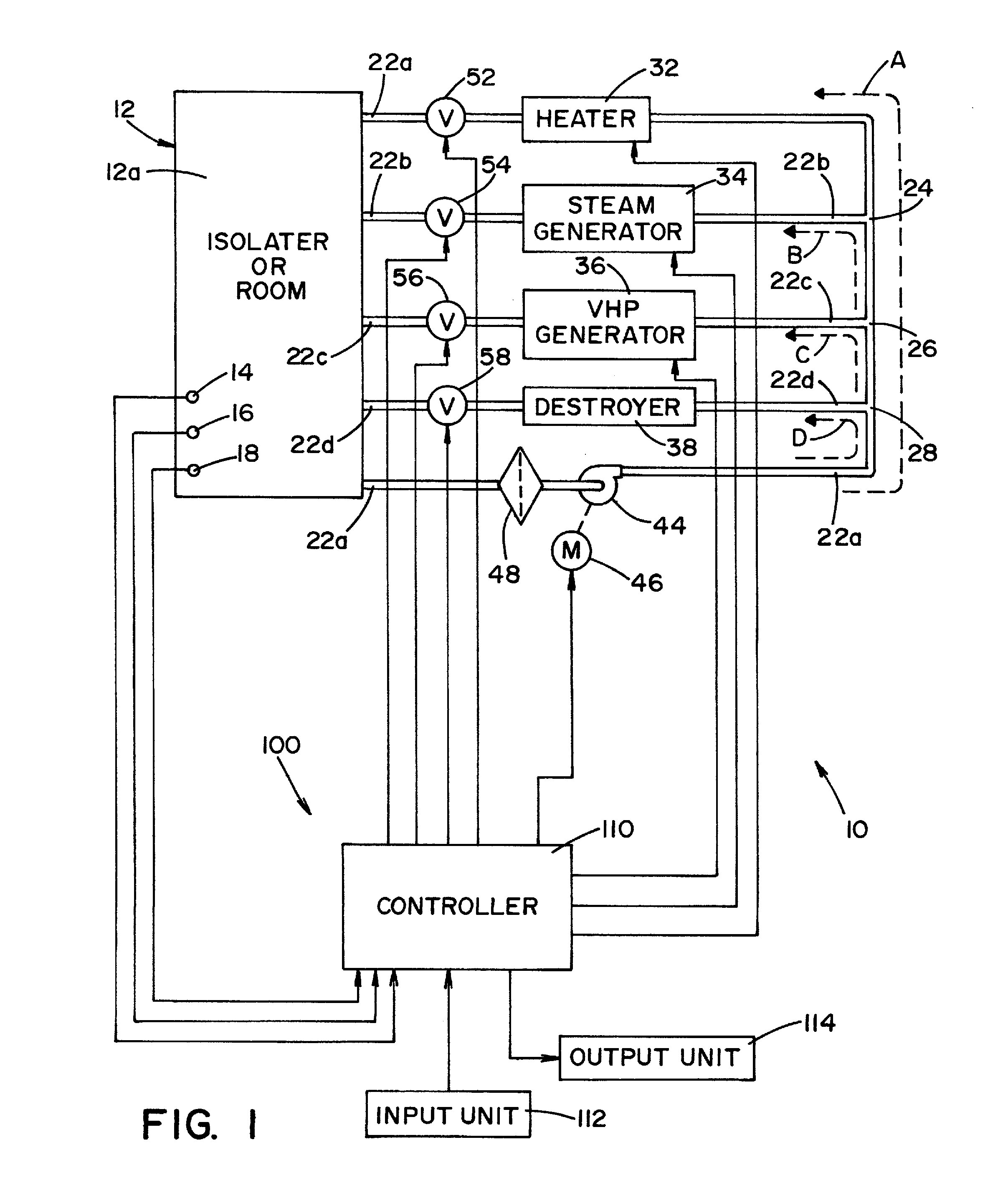
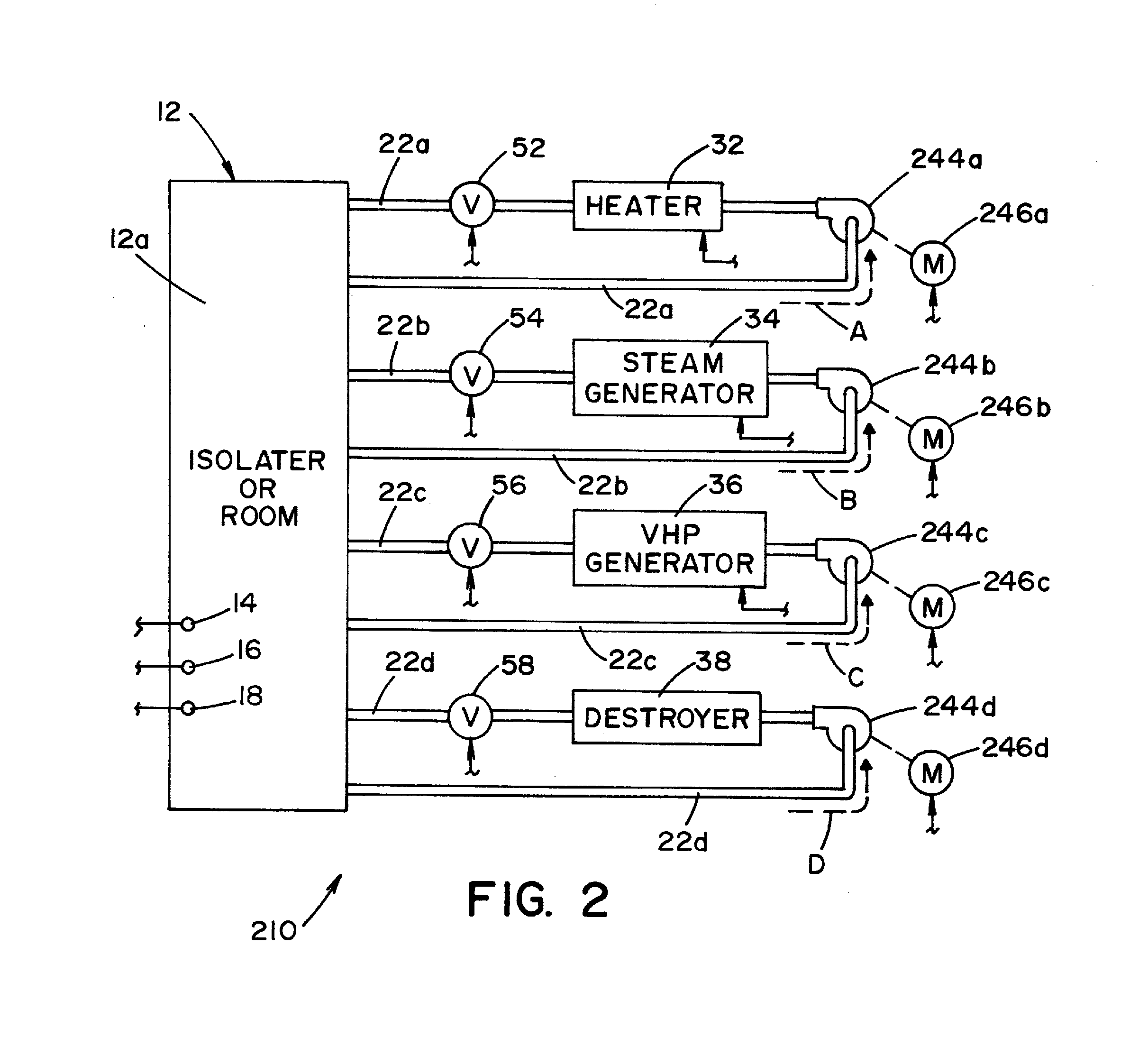
[0017]Referring now to the drawings wherein the showings are for the purpose of illustrating a preferred embodiment of the invention only, and not for the purpose of limiting same, FIG. 1 shows a sterilization system 10, illustrating a preferred embodiment of the present invention. The present invention will be described with reference to using vaporized hydrogen peroxide (VHP) as a sterilant and combining VHP with humidity to disinfect or deactivate articles. However, it is contemplated that the sterilant may be one or more vaporous sterilants or a combination of one or more vaporous sterilants with one or more gaseous sterilants. By way of example and not limitation, the vaporous sterilant may include one or more of the following: peracetic acid, bleach and ammonia and the gaseous sterilant may include one or more of the following: ozone, chlorine dioxide, oxides of nitrogen and ethylene oxide. It is also contemplated that the sterilant may be one or more of the chemicals disclose...
PUM
 Abstract
Description
Claims
Application Information