
Electrode and electrode structural body

a technology of electrodes and structural bodies, applied in the direction of oxygen/ozone/oxide/hydroxide, electrical discharge ozone preparation, etc., can solve the problems of disadvantageous deterioration of insulating substances, high energy loss, and significant reduction of insulation strength, so as to simplify the structural body of the retainer and reduce the electric field

Inactive Publication Date: 2015-09-24
NGK INSULATORS LTD
View PDF1 Cites 0 Cited by
  • Summary
  • Abstract
  • Description
  • Claims
  • Application Information

AI Technical Summary

Benefits of technology

The patent describes an electrical connector design that reduces the generation of unnecessary discharge, improves durability and energy loss, while also reducing the overall size of the connector. Connectors using a retainer can have a reduced creepage distance and lowered electric field, simplifying the structure of the retainer.

Problems solved by technology

Therefore, when a boundary between the insulating body and the sealant is deteriorated due to temperature change or the like, the insulation strength is significantly reduced.
Therefore, the insulating substance is disadvantageously deteriorated due to ozone generation.
WO 2008 / 108331, the electric field strength is increased at the boundary between a portion having the sealant and a portion not having the sealant, and undesirable creeping discharge is often caused.
This leads to high energy loss and affects the durability.
Therefore, the structural body is often complicated, and the creepage is disadvantageously deteriorated.

Method used


Image

  • Electrode and electrode structural body
  • Electrode and electrode structural body
  • Electrode and electrode structural body

Examples


example 1

[0079]

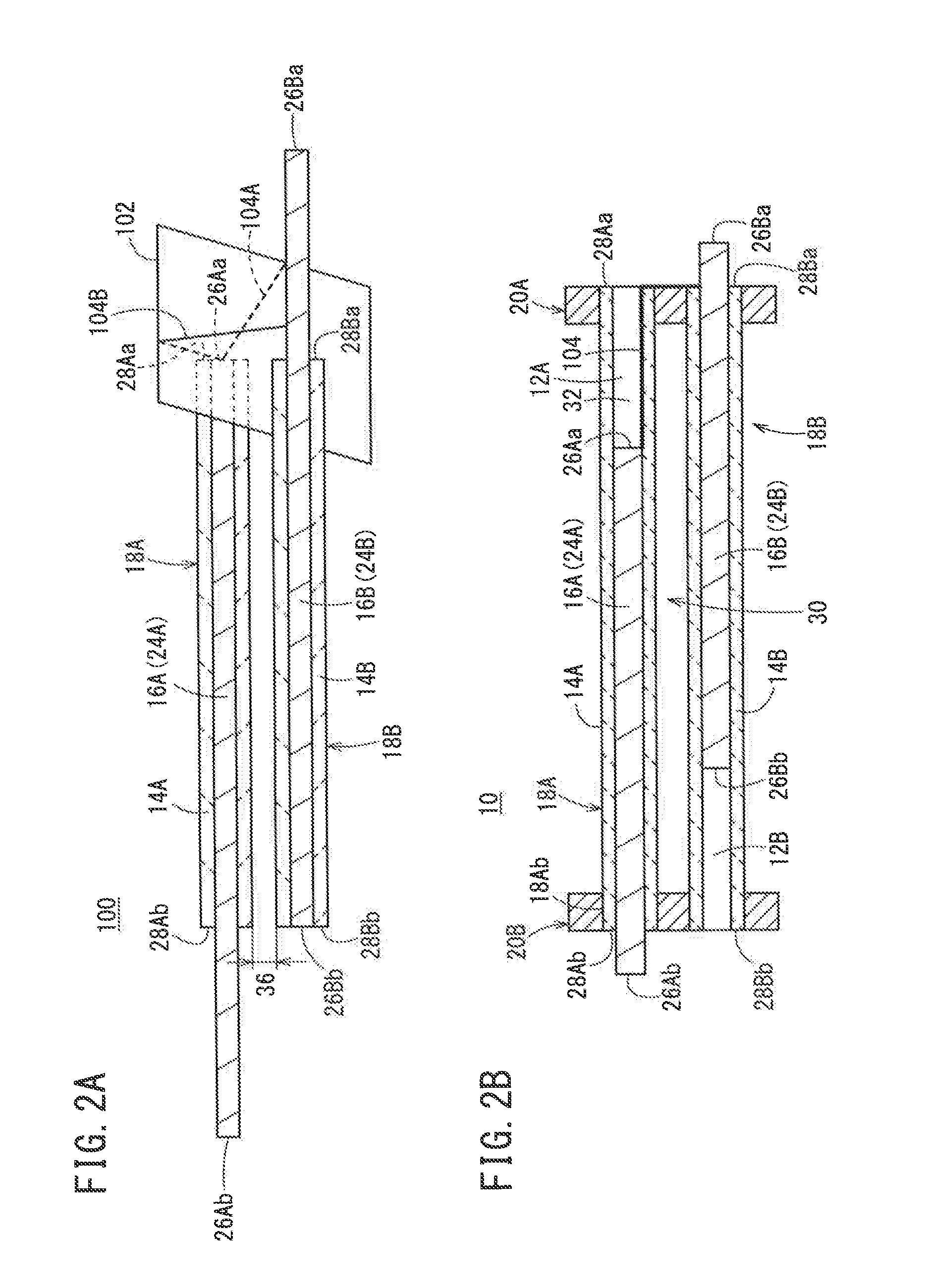
[0080]As shown in FIG. 3B, in the electrode structural body of Reference Example 1, an insulating material 108, which has a permittivity equal to that of the first insulating body 14A, is inserted between the one end surface 26Aa of the first conducting rod 24A and the one end surface 28Aa of the first insulating body 14A in the first hollow portion 12A of the first electrode 18A. Thus, a solid structure is formed.

[0081]As shown in FIG. 5B, the electrode structural body of

[0082]Reference Example 2 has the solid structure similar to that of Reference Example 1, and has the supporting member 106 similar to the supporting member 106 of Example 2.

[0083]As shown in FIG. 6B, the electrode structural body of Reference Example 3 has the solid structure similar to that of Reference Example 1, and has the supporting member 106 similar to the supporting member 106 of Example 3.

[0084]In comparison between Example 1 and Reference Example 1, as shown in FIGS. 3A to 4B, the electric field st...


PUM

PropertyMeasurementUnit
thicknessaaaaaaaaaa
thicknessaaaaaaaaaa
outer diameteraaaaaaaaaa

Abstract

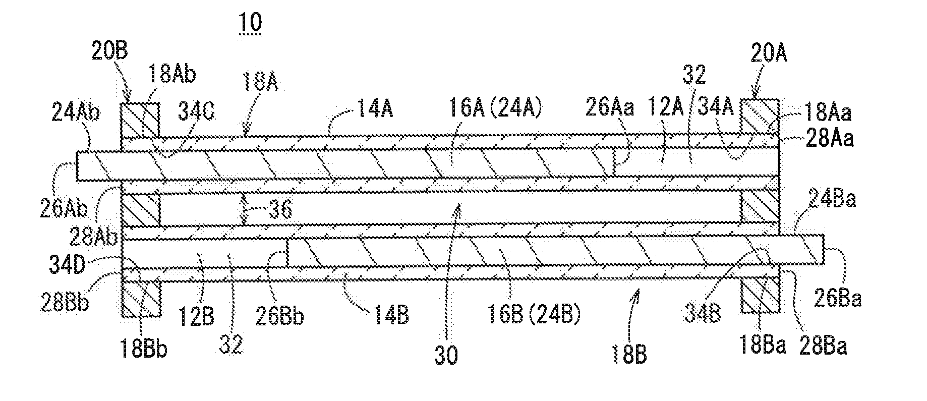
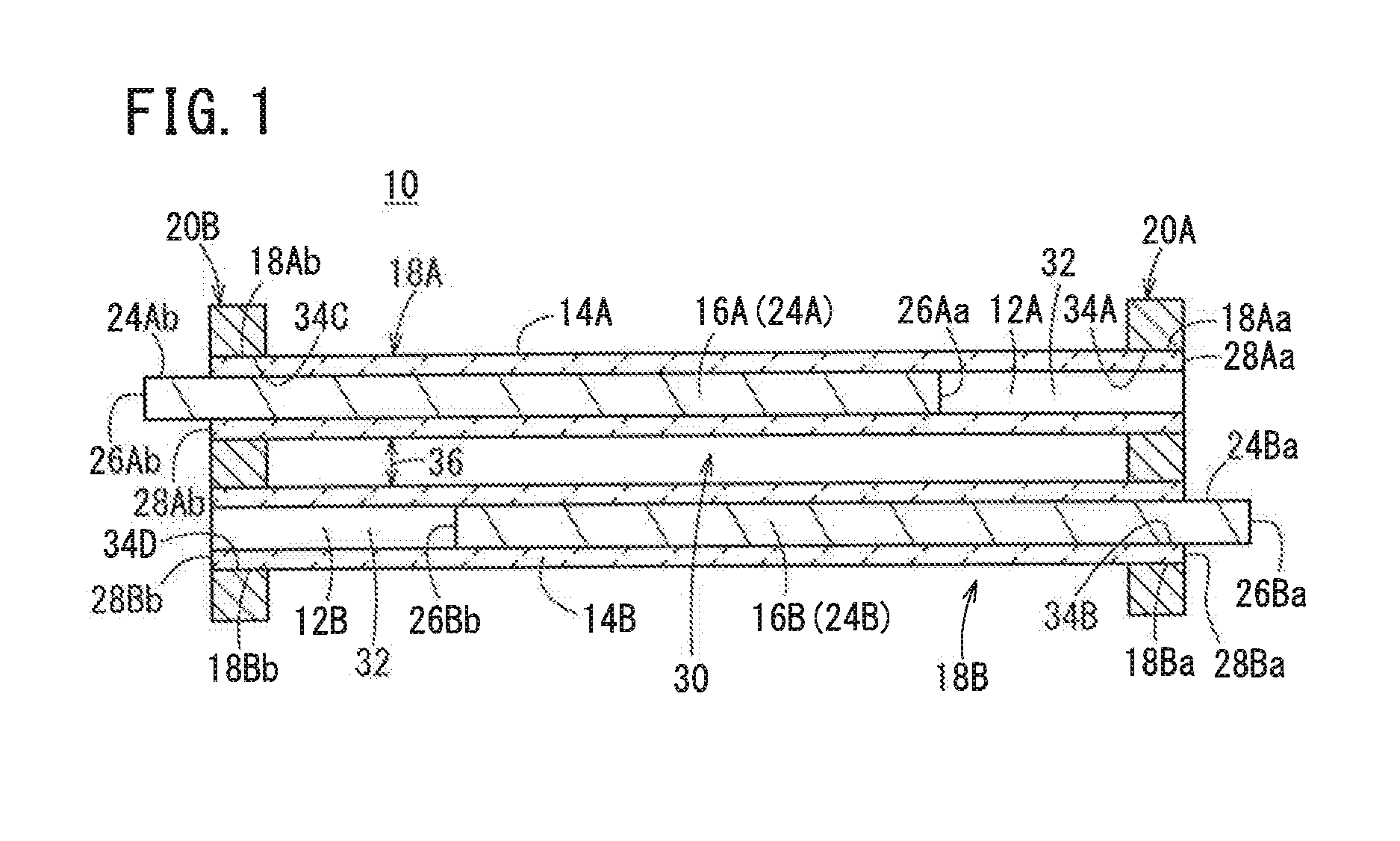
An electrode structural body includes a first electrode and a second electrode, and further includes a first retainer and a second retainer for fixing the first electrode and the second electrode. The first electrode and the second electrode are separated from each other, their axial directions being parallel to each other. The first electrode contains a first insulating body having a first hollow portion and a first conducting body located in the first hollow portion. The second electrode contains a second insulating body having a second hollow portion and a second conducting body located in the second hollow portion. At least in the first electrode, at least one end surface of the first conducting body is positioned inside the first hollow portion at a distance from one end surface of the first insulating body.

Description

CROSS-REFERENCE TO RELATED APPLICATION[0001]This application is based upon and claims the benefit of priority from Japanese Patent Application No. 2014-058387 filed on Mar. 20, 2014, the contents of which are incorporated herein by reference.BACKGROUND OF THE INVENTION[0002]1. Field of the Invention:[0003]The present invention relates to an electrode and an electrode structural body containing an insulating body and a conducting body suitable for use, e.g., in a dielectric-barrier discharge electrode or an ozone generator.[0004]2. Description of the Related Art:[0005]For example, low-temperature plasma generators described in Japanese Laid-Open Patent Publication No. 08-185955 and International Publication No. WO 2008 / 108331 have been known as a structural body containing an insulating body and a conductive material.[0006]In the low-temperature plasma generator described in Japanese Laid-Open Patent Publication No. 08-185955, a rod-shaped conducting body is inserted into a through-h...

Claims


Application Information

Patent Timeline
Patent Type & Authority Applications(United States)
IPC IPC(8): B01J19/08C01B13/11
CPCB01J19/088C01B13/115B01J2219/083B01J2219/0815B01J2219/0809C01B13/11C01B2201/14C01B2201/22C01B2201/62H05H1/2418H05H1/2441
Inventor KONDO, YOSHIMASAYOKOI, SHOJITERAZAWA, TATSUYATAKASE, NAOYA
Owner NGK INSULATORS LTD
Learn More