Working head moving device

Active Publication Date: 2015-09-24
SEIBU JIDO KIKI
View PDF4 Cites 10 Cited by
  • Summary
  • Abstract
  • Description
  • Claims
  • Application Information

AI Technical Summary

Benefits of technology

[0021]According to the present invention, the working head moving device adopted in the working apparatus for performing machining such as grinding and super-finishing on a workpiece supported on the work setting section having the underside-abutting portion and the side-abutting portion is capable of maintaining

Problems solved by technology

In this case, if only the mechanism for allowing movement along the axis of rotation P is adopted for the cup-type grinding wheel 104, a one-sided contact phenomenon, namely a phenomenon in which the cup-type grinding wheel 104 is only partly (only at its left end as viewed in FIG. 12) brought into contact with the workpiece W, will take pl

Method used


Image

  • Working head moving device
  • Working head moving device
  • Working head moving device

Examples


Embodiment Construction

[0037]Hereinafter, embodiments of the present invention will be explained with reference to drawings.

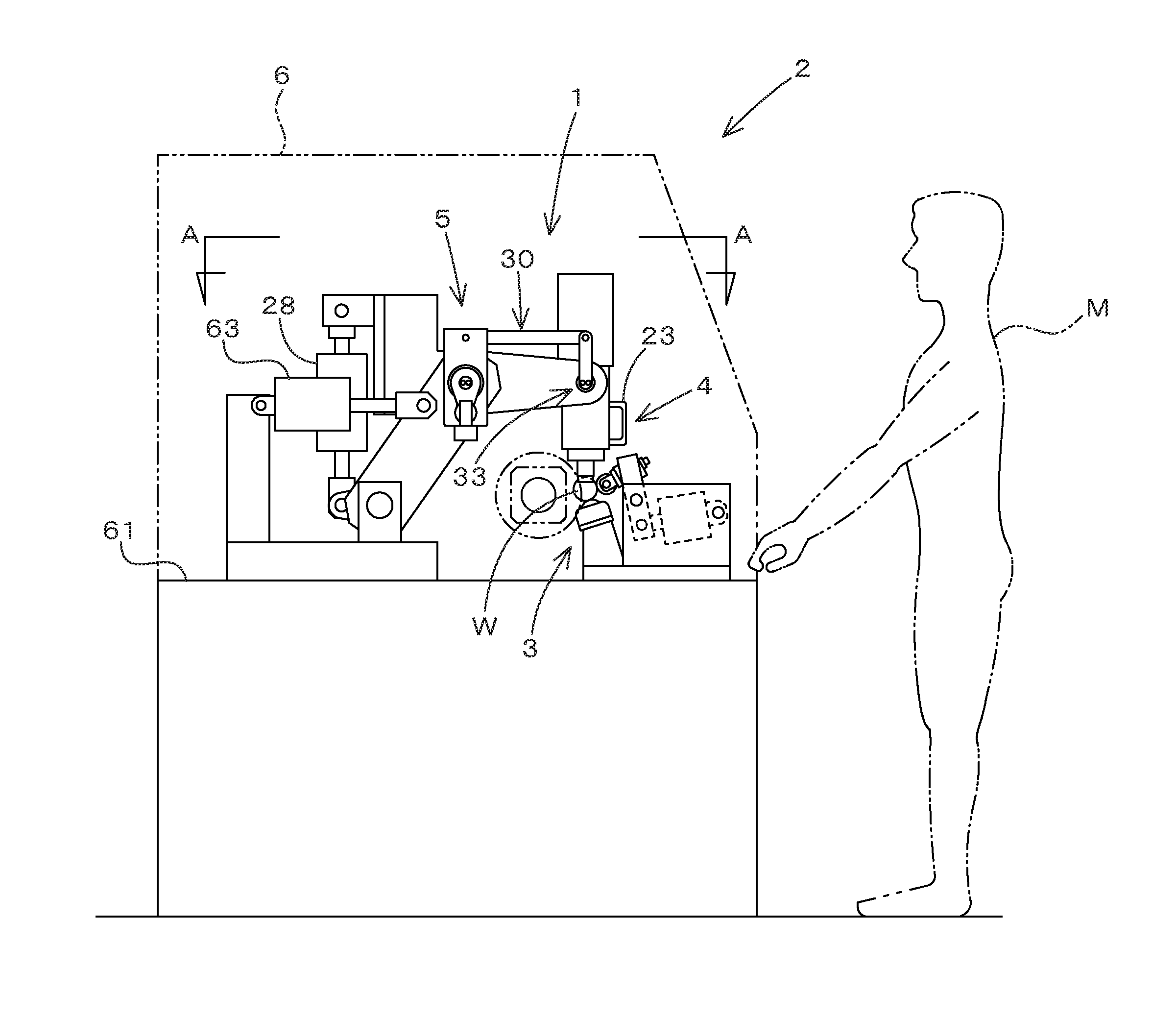
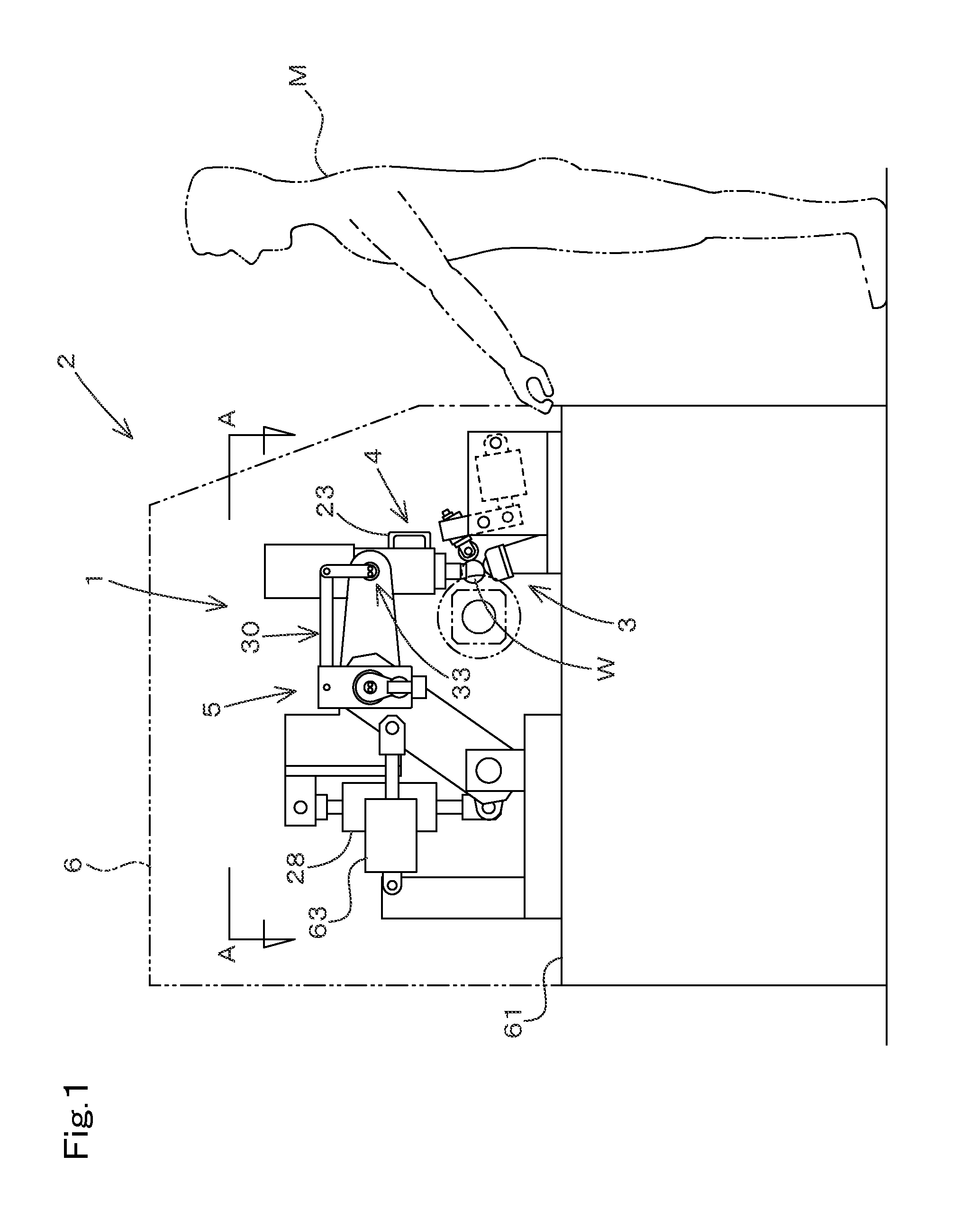
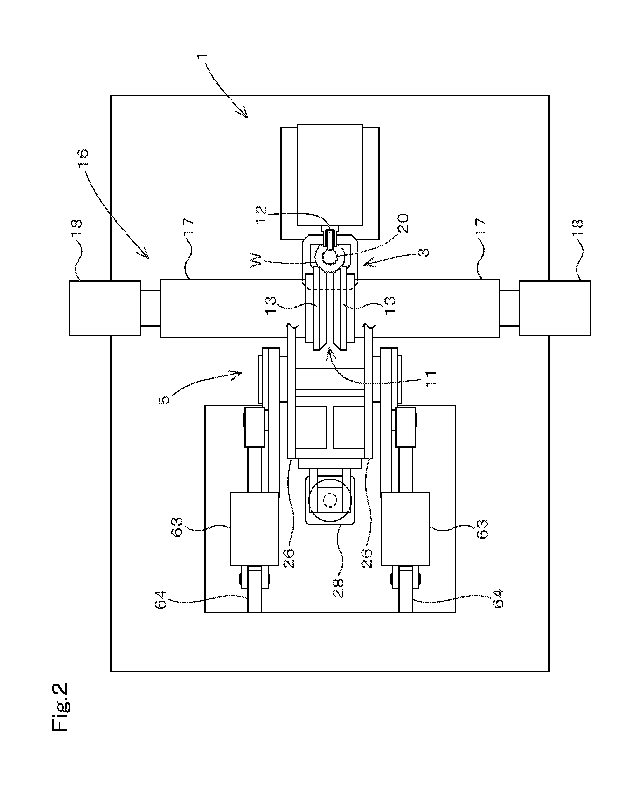
[0038]FIGS. 1 to 10B show a working head moving device 1 in accordance with one embodiment of the present invention. This embodiment will be described in respect of a case where a raw spherical body is a workpiece W. Moreover, this embodiment will be described in respect of a case where the working head moving device 1 pursuant to the present invention is incorporated in a working apparatus 2 for performing spherical-surface polishing process such as grinding and super-finishing on the workpiece W.

[0039]As shown in FIG. 1, the working head moving device 1 pursuant to the present invention comprises: a work setting section 3 for effecting positioning of the workpiece W; a working head 4 for performing machining on the workpiece W held by the work setting section 3; and a head moving system 5 for moving the working head 4 relative to the workpiece W. The upper half of the apparatus is ...


PUM


Abstract

The working head moving device adopted in the working apparatus for machining workpiece supported by the work setting section having the underside-abutting portion and the side-abutting portion can maintain proper machining conditions with adaptability to decrease in size of workpiece entailed by proceeding of machining, can perform machining on workpiece with high uniformity and precision, and can move the working head without causing damage to workpiece. There is provided the head moving system for moving the working head between the working-state position and the retracted-state position, and the head moving system has the trunnion support portion which allows the working head to rock about its oscillation axis perpendicular to the rotation axis of the rotary tool when the working head is pressed against workpiece in conformity with decrease of workpiece size entailed by proceeding of machining, thereby maintaining the angle of intersection of workpiece-contacted surface and the rotation axis invariant.

Description

CROSS-REFERENCE TO RELATED APPLICATION[0001]The present application claims priority under 35 U.S.C. §119 to Japanese Patent Application No. 2014-58130, filed Mar. 20, 2014. The contents of this application are incorporated herein by reference in their entirety.FIELD OF INVENTION[0002]The present invention relates to a working head moving device suitable for use in a working apparatus for performing grinding, super-finishing, and so forth on a spherical body.BACKGROUND OF THE INVENTION[0003]In the course of the manufacture of spherical products, heretofore it has been customary to adopt a method involving a step of holding a plurality of workpieces (raw spherical bodies) by two parallel grinding plates in sandwich style and a step of effecting relative parallel movement of the two grinding plates to cause the workpieces to roll (to grind the entire spherical surfaces) for increasing the degree of sphericity.[0004]In this regard the present applicants have developed a working apparatu...

Claims


Application Information

Patent Timeline
IPC IPC(8): B24B11/02B24B41/02
CPCB24B41/02B24B11/02
Inventor KONDOH, GISABURO
Owner SEIBU JIDO KIKI
Why Eureka
Try Eureka