
Complex apparatus of reverse electrodialysis equipment and desalination plant and method for improving power density thereof

a reverse electrodialysis and equipment technology, applied in electrodialysis, energy-based wastewater treatment, refrigeration components, etc., can solve the problems of low power generation efficiency, unbalanced design of complex systems, and low power density produced by electrodialysis equipment, so as to improve power density and improve power density , the effect of enhancing the recycling of high-concentration sea water

Inactive Publication Date: 2015-09-24
KOREA INST OF SCI & TECH
View PDF3 Cites 5 Cited by
  • Summary
  • Abstract
  • Description
  • Claims
  • Application Information

AI Technical Summary

Benefits of technology

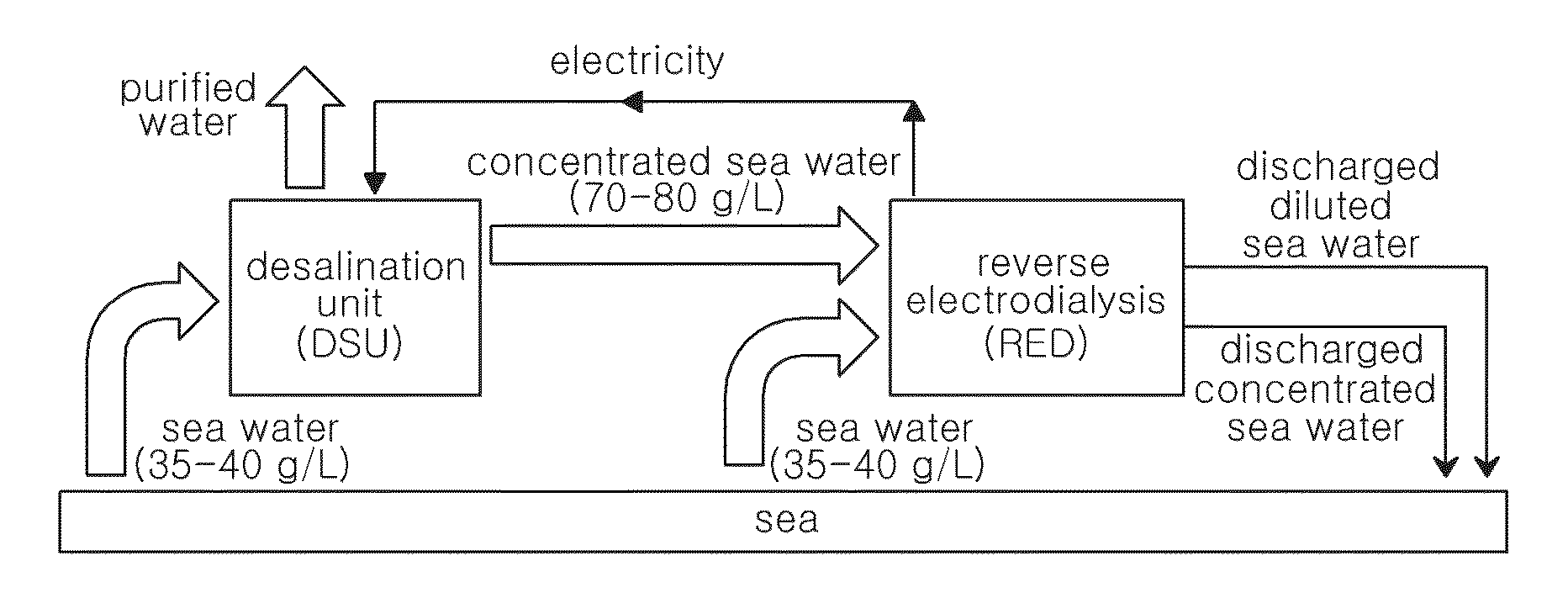
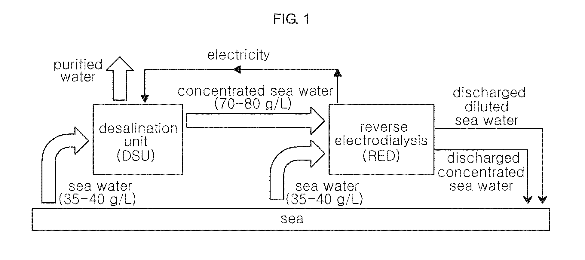
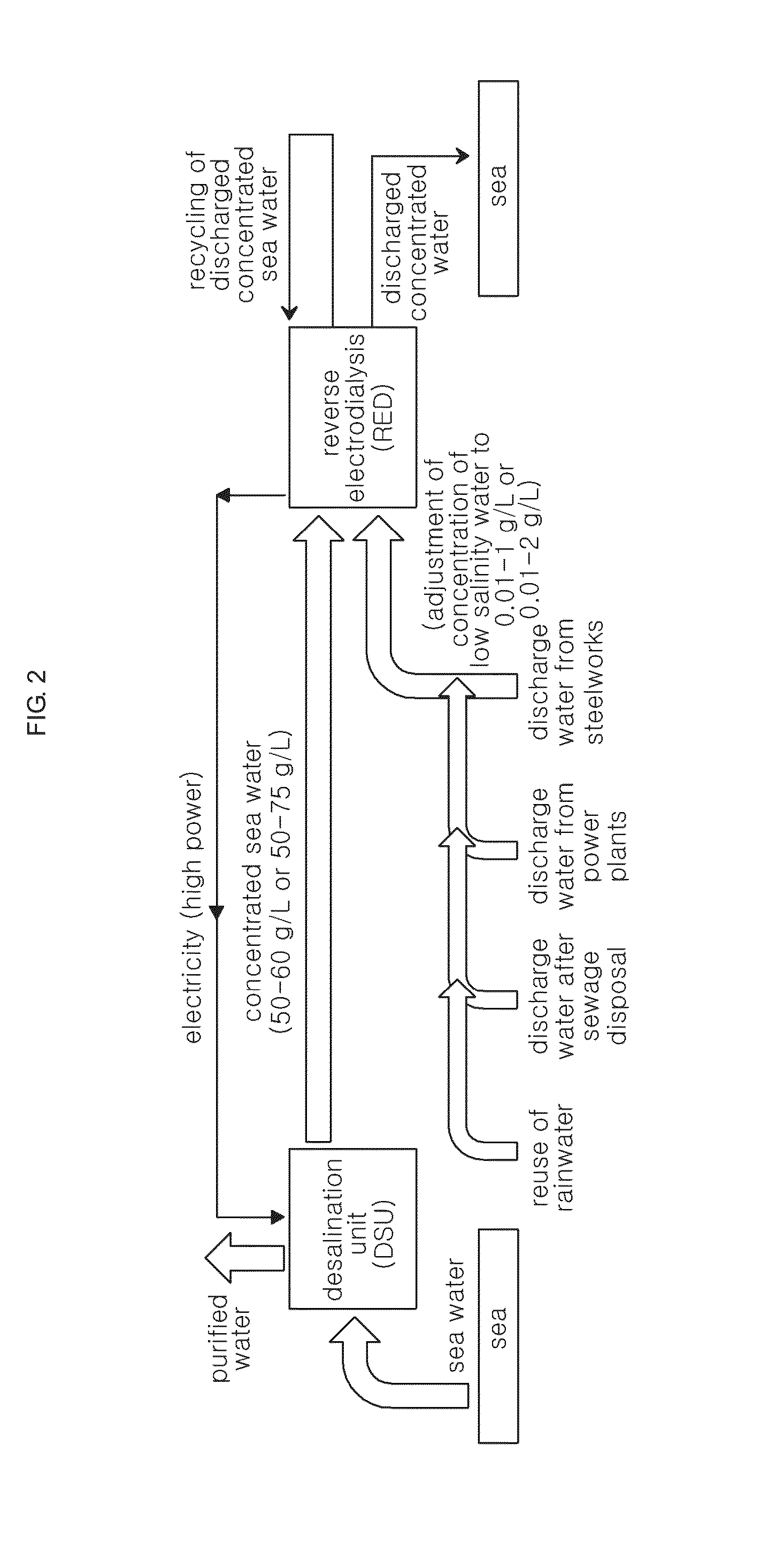
The present patent provides a method and apparatus for enhancing the recycling of high-concentration sea water in a complex system of desalination plant and reverse electrodialysis equipment, while also significantly improving the power density produced by the reverse electrodialysis equipment even with increased resistance.

Problems solved by technology

According to an observation by the inventors of the present disclosure, the conventional complex system of desalination plant and reverse electrodialysis equipment uses a sea water directly as a low-concentration salt solution, but due to a high concentration of the sea water (about 35 to 40 g / L), a power density produced by the electrodialysis equipment is very low, which in turn results in a low power generation efficiency.
In addition, considering that the conventional complex system of desalination plant and reverse electrodialysis equipment should be constructed in a large scale, such low power generation efficiency may be very disadvantageous in economical point of view, and may lead to an unbalanced design of the complex system.
Moreover, the conventional technique is just focusing on a concentration difference between a high salinity water and a low salinity water but does not recognize other important factors such as a concentration ratio, resistance, OCV, power density change, etc. of the high salinity water and the low salinity water.

Method used


Image

  • Complex apparatus of reverse electrodialysis equipment and desalination plant and method for improving power density thereof
  • Complex apparatus of reverse electrodialysis equipment and desalination plant and method for improving power density thereof
  • Complex apparatus of reverse electrodialysis equipment and desalination plant and method for improving power density thereof

Examples


experiment 1

Example and Comparative Example

[0079]In this experiment, for the complex system of a desalination plant and a reverse electrodialysis equipment according to an embodiment of the present disclosure [Example: this will be called DSU-RED (concentrated sea water / fresh water)], the change of a power density was observed in comparison to a comparative system [Comparative Example 1: this will also be called a DSU-RED (concentrated sea water / sea water)] and a reverse electrodialysis equipment not using a desalination plant [Comparative Example 2: this will also be called a RED (sea water / fresh water)].

[0080]Reverse electrodialysis equipment was firstly configured.

[0081]FIG. 4 is a schematic diagram showing a unit cell of the reverse electrodialysis equipment of the complex apparatus according to an embodiment of the present disclosure.

[0082]Referring to FIG. 4, an anion exchange membranes [Selemion™, AMV, about 5 cm×about 5 cm, about 120 μm] is interposed between cation exchange membranes [...

experiment 2

[0101]In Experiment 2, a salt concentration (Cs) of concentrated sea water was set to about 50 g / L, and then a concentration ratio (Cs / Cr), OCV, and relative Pmax (Rel. Pmax) were observed while changing a salt concentration (Cr) of low salinity water. The relative Pmax (Rel. Pmax) means a ratio of Pmax of each Example with respect to Pmax of Comparative Example 3. That is, Rel. Pmax of Comparative Example 3 is 1. Rel. Pmax of each Example is Pmax of each Example / Pmax of Comparative Example 3.

[0102]Table 3 shows OCV and Rel. Pmax according to the change of Cs / Cr when the concentrated sea water has a salt concentration (Cs) of about 50 g / L. For reference, the Examples and Comparative Example below belong to Experiment 2.

TABLE 3saltconcen-trationCsCrOCVRel.(g / L)(g / L)Cs / Cr(V)PmaxComparative50301.70.0223317061.00Example 3Example 250202.50.0401039353.225003287Example 350192.60.0423577943.597682771Example 450182.80.0447352184.01287198Example 550172.90.0472505434.476821725Example 650163.10...

experiment 3

[0106]In Experiment 3, the salt concentration (Cs) of concentrated sea water was set to about 60 g / L, a concentration ratio (Cs / Cr), OCV, and relative Pmax (rel. Pmax) were observed while changing a salt concentration (Cr) of low salinity water.

[0107]The relative Pmax (Rel. Pmax) is a ratio of Pmax of each Example with respect to Pmax of Comparative Example 4. In other words, Rel. Pmax of Comparative Example 4 is 1. Rel. Pmax of each Example is Pmax of each Example / Pmax of Comparative Example 4.

[0108]Table 4 shows OCV and Rel. Pmax according to the change of Cs / Cr when the concentrated sea water has a salt concentration (Cs) of about 60 g / L.

[0109]For reference, the Examples and Comparative Example below belong to Experiment 3.

TABLE 4saltconcen-trationCsCrOCVRel.(g / L)(g / L)Cs / Cr(V)PmaxComparative60302.00.030303351.00Example 4Example 2760203.00.0480755792.516910413Example 2860193.20.0503294382.758435816Example 2960183.30.0527068623.025192634Example 3060173.50.0552221873.320824477Exampl...


PUM

PropertyMeasurementUnit
concentrationaaaaaaaaaa
salt concentrationaaaaaaaaaa

Abstract

In a complex system including a desalination plant and a reverse electrodialysis equipment, a concentrated sea water discharged from the desalination plant having a salt concentration of about 50 to 75 g / L or about 50 to 60 g / L is provided as a high-concentration salt solution of the reverse electrodialysis equipment while low salinity water having a salt concentration of about 0.01 to 2 g / L, most preferably about 0.01 to 1 g / L, is provided as a low-concentration salt solution of the reverse electrodialysis equipment. Thereby, a recycling degree of a concentrated sea water may be enhanced as well as a power density produced by the complex system is significantly improved.

Description

CROSS-REFERENCE TO RELATED APPLICATION[0001]This application claims priority to Korean Patent Application No. 10-2014-0033499, filed on Mar. 21, 2014, and all the benefits accruing therefrom under 35 U.S.C. §119, the contents of which in its entirety are herein incorporated by reference.BACKGROUND[0002]1. Field[0003]The present disclosure relates to a complex apparatus of reverse electrodialysis equipment and desalination plant and a method for improving a power density thereof.[0004]2. Description of the Related Art[0005]Power may be produced using a reverse electrodialysis (hereinafter, also referred to as RED).[0006]That is, in the reverse electrodialysis, electric energy may be produced by using selective ion penetration due to a concentration difference through a membrane (or, ion exchange membrane) between two ion solutions having different ion concentrations, as well known in the art.[0007]For example, reverse electrodialysis equipment may include a membrane stack having cati...

Claims


Application Information

Patent Timeline
Patent Type & Authority Applications(United States)
IPC IPC(8): C02F9/00C02F1/14C02F1/469
CPCC02F9/00C02F1/4693C02F2201/46C02F2103/08C02F2201/32C02F1/14C02F2103/007C02F2209/05Y02W10/37Y02A20/142Y02A20/124C02F1/44F03G7/04H02N11/00Y02E10/30
Inventor JANG, JONG HYUNKIM, HYOUNG-JUHNNAM, SUK WOORYU, JAEYUNEYOO, SUNG JONGYOON, SUNG PILLIM, TAE HOONCHO, EUN AECHOI, INSOOHAN, JONGHEEHAN, JUN YOUNGHENKENSMEIER, DIRK
Owner KOREA INST OF SCI & TECH
Learn More