
Method for performing a charge exchange in an internal combustion engine

a charge exchange and internal combustion engine technology, applied in combustion engines, valve arrangements, electrical control, etc., can solve the problems of supercharged or turbocharged engines, torque drop, and reducing power output, so as to reduce the turbine pressure ratio, minimize fuel consumption, and improve the torque/power output density of engines

Active Publication Date: 2015-09-24
FORD GLOBAL TECH LLC
View PDF3 Cites 1 Cited by
  • Summary
  • Abstract
  • Description
  • Claims
  • Application Information

AI Technical Summary

Benefits of technology

The patent describes a method and system for improving engine performance by opening exhaust valves during the charge exchange to increase the pressure and reduce scavenging. This may result in increased low end torque without increasing exhaust gas temperature. Overall, the method and system may provide better engine performance without sacrificing power output.

Problems solved by technology

However, such a supercharged or turbocharged engine, under low engine speed conditions, may experience torque drop due to a decrease in exhaust-gas mass flow which may subsequently lower a turbine pressure ratio.
For example, scavenging losses may occur during valve overlap, which may prevent a full charge of fresh air from entering the cylinder and participating in combustion, thus reducing power output.
Moreover, the large valve overlap needed to overcome torque deficit at low engine speeds may not be viable in internal combustion engines with high compression ratios, such as diesel engines, due to the proximity of the piston to the valves as it moves toward top dead center.
An exhaust-gas turbocharger with a smaller cross-section may be able to generate charge pressure at low exhaust-gas flow rates, but may consequently shift the torque drop further toward lower engine speeds.

Method used


Image

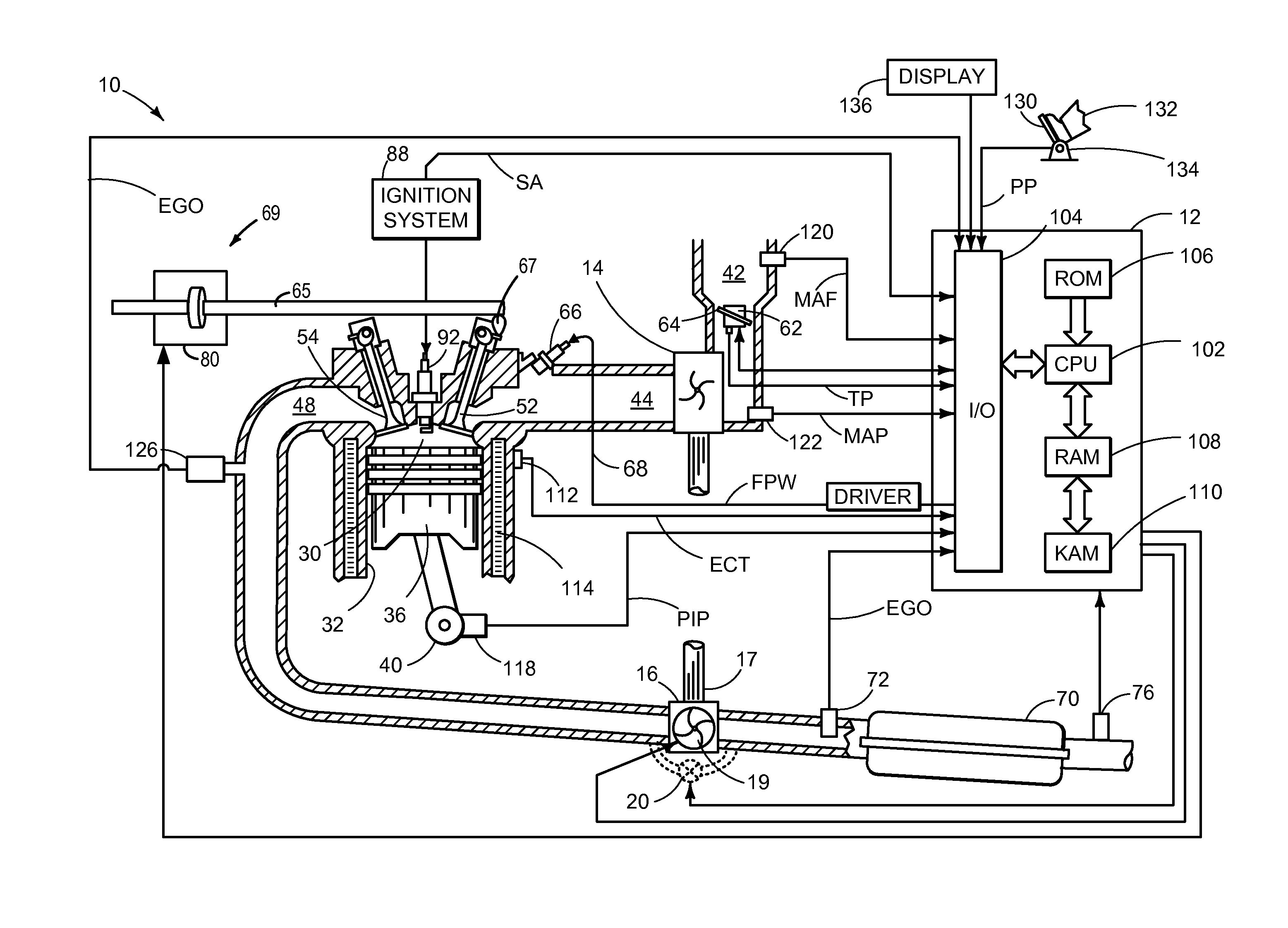
  • Method for performing a charge exchange in an internal combustion engine
  • Method for performing a charge exchange in an internal combustion engine
  • Method for performing a charge exchange in an internal combustion engine

Examples


first embodiment

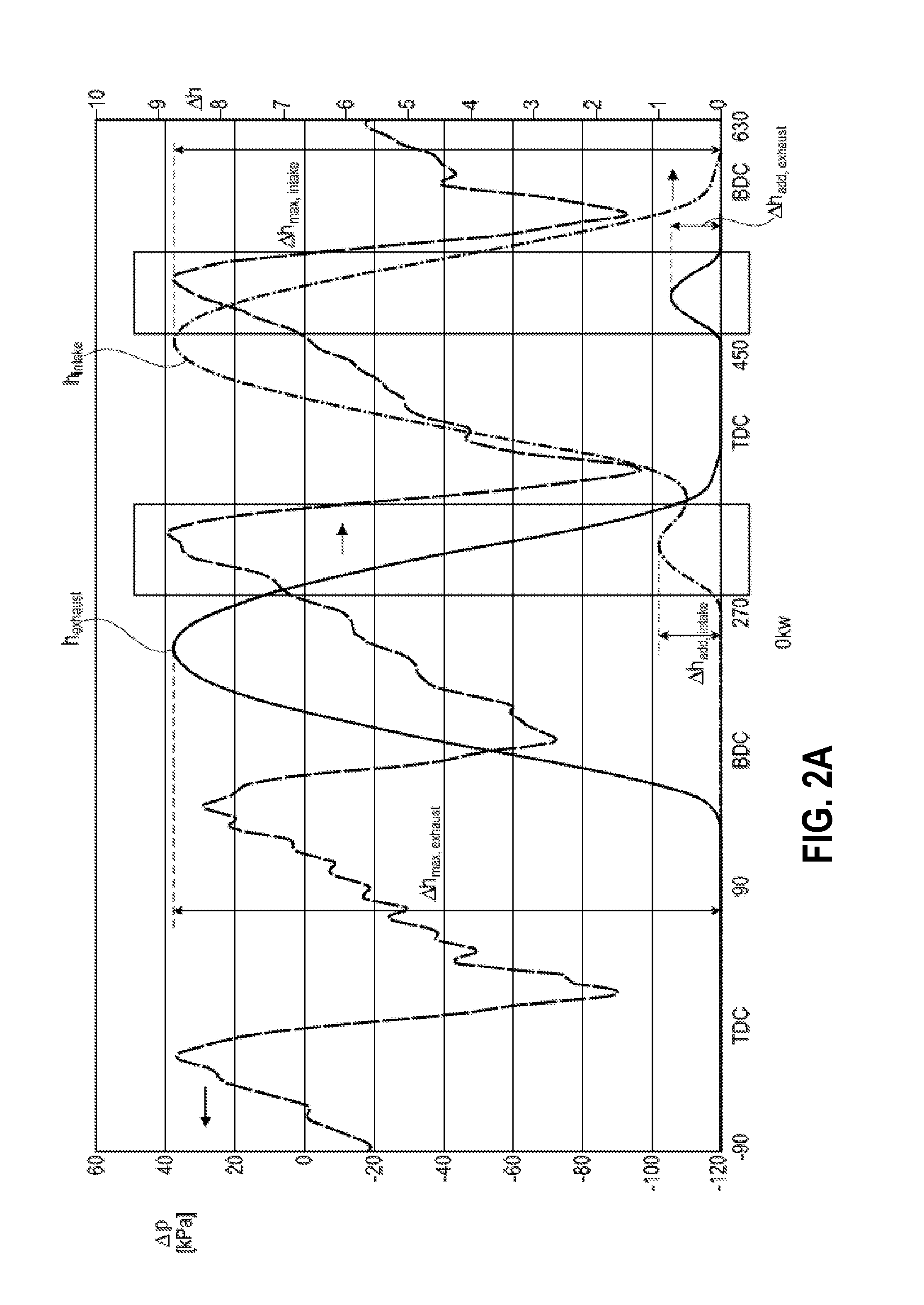
[0102]FIG. 2A shows, in a diagram, the valve lift curves hintake, hexhaust of an inlet valve and of an outlet valve in accordance with the method. Also illustrated is the pressure difference Δp between the intake system and the exhaust-gas discharge system, that is to say between the inlet side and the outlet side.

[0103]During the charge exchange, the exhaust gas may be evacuated from the cylinder by virtue of the outlet valve being opened and performing the maximum valve lift Δhmax,exhaust. The inlet valve is consequently opened in order to fill the cylinder with fresh air again, wherein the inlet valve performs the maximum valve lift Δhmax,intake during the course of the charge exchange.

[0104]The inlet valve is in this case actuated such that said inlet valve performs an additional valve lift Δhadd,intake, specifically before the inlet valve performs the maximum valve lift Δhmax,intake during the course of the charge exchange and before the piston reaches top dead center during th...

second embodiment

[0111]FIG. 2B shows, in a diagram, the valve lift curves hintake, hexhaust of an inlet valve and of an outlet valve in accordance with the method. The pressure difference Δp between the intake system and the exhaust-gas discharge system is likewise illustrated.

[0112]It is sought to explain only the differences in relation to the method variant illustrated in FIG. 2A, for which reason reference is otherwise made to FIG. 2A. The same reference signs are used.

[0113]By contrast to the method variant illustrated in FIG. 2A, it is the case in the method variant illustrated in FIG. 2B that an additional valve lift Δhadd,exhaust of the outlet valve may be omitted.

[0114]An additional valve lift Δhadd,exhaust of the outlet valve may not be used either for increasing the mass flow supplied to the turbine for the purposes of increasing torque or for cooling said mass flow for the purposes of lowering the turbine inlet temperature.

[0115]Turning now to FIG. 3, an example method flowchart 300 for ...


PUM


Abstract

A method and system for perform a charge exchange in internal combustion engine comprising an additional intake and exhaust valve lifts performed during positive pressure gradients between the intake and exhaust systems to reducing scavenging losses and increase torque during low engine speeds.

Description

CROSS REFERENCE TO RELATED APPLICATIONS[0001]The present application claims priority to German Patent Application No. 102014205414.1, filed Mar. 24, 2014, the entire contents of which are hereby incorporated by reference for all purposes.FIELD[0002]The present disclosure relates a method and system of performing a charge exchange in an internal combustion engine.BACKGROUND SUMMARY[0003]Engines may use a turbocharger or a supercharger to improve engine torque / power output density and minimize fuel consumption. In one example, a turbocharger may include a compressor and a turbine connected by a drive shaft, where the turbine is coupled to an exhaust manifold side and the compressor is coupled to an intake manifold side. However, such a supercharged or turbocharged engine, under low engine speed conditions, may experience torque drop due to a decrease in exhaust-gas mass flow which may subsequently lower a turbine pressure ratio.[0004]One approach to address the issue of torque drop un...

Claims


Application Information

Patent Timeline
IPC IPC(8): F02D13/02
CPCF02D13/0207F02B25/145F02D13/0273F02D41/0007F02D2041/001Y02T10/12
Inventor KEMMERLING, JOERGSOMMERHOFF, FRANZ ARNDKINDL, HELMUT MATTHIASSMILJANOVSKI, VANCOHERUDEK, CLAUDIA KATHARINAKUSKE, ANDREAS
Owner FORD GLOBAL TECH LLC
Learn More