Actuator motion control

a technology of actuators and actuators, applied in the direction of electric control, machine/engine, operating means/releasing devices of valves, etc., can solve problems such as deviations from desired values

Active Publication Date: 2015-09-24
GM GLOBAL TECH OPERATIONS LLC
View PDF5 Cites 15 Cited by
  • Summary
  • Abstract
  • Description
  • Claims
  • Application Information

AI Technical Summary

Problems solved by technology

While the generated magnetic fluxes and magnetic forces are theoretically proportional to electrical current applied to the solenoid devices, residual magnetic flux within the fuel injectors can result in deviations from desired values.

Method used


Image

  • Actuator motion control
  • Actuator motion control
  • Actuator motion control

Examples


Embodiment Construction

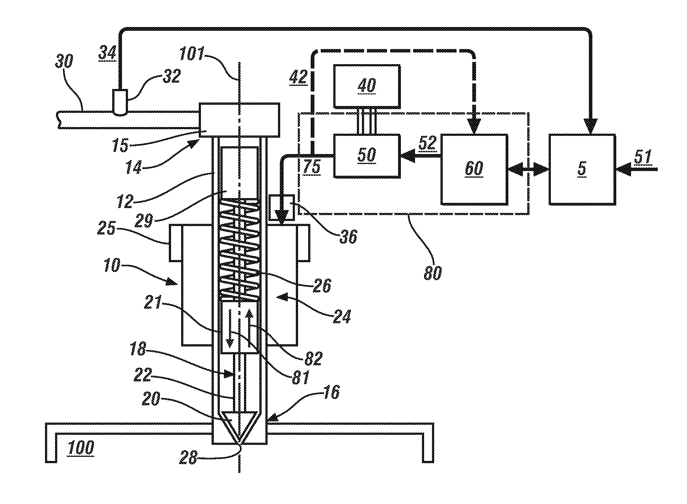
[0013]This disclosure describes the concepts of the presently claimed subject matter with respect to an exemplary application to linear motion fuel injectors. However, the claimed subject matter is more broadly applicable to any linear or non-linear electromagnetic actuator that employs an electrical coil for inducing a magnetic field within a magnetic core resulting in an attractive force acting upon a movable armature. Typical examples include fluid control solenoids, gasoline or diesel or CNG fuel injectors employed on internal combustion engines and non-fluid solenoid actuators for positioning and control.

[0014]Referring now to the drawings, wherein the showings are for the purpose of illustrating certain exemplary embodiments only and not for the purpose of limiting the same, FIG. 1 schematically illustrates a non-limiting exemplary embodiment of an electromagnetically-activated direct-injection fuel injector 10. While an electromagnetically-activated direct-injection fuel inje...


PUM


Abstract

A system for controlling actuation of an electromagnetic actuator includes an actuator having an electrical coil, a magnetic core, and an armature. A controllable drive circuit is responsive to an electric power flow signal for driving current through the electrical coil to actuate the armature. A control module includes an armature motion observer configured to determine an armature motion parameter in the actuator based upon a magnetic flux within the actuator and a predetermined mechanical equation of motion corresponding to the actuator and adapt the electric power flow signal based on the armature motion parameter.

Description

CROSS REFERENCE TO RELATED APPLICATIONS[0001]This application claims the benefit of U.S. Provisional Application No. 61 / 955,963, filed on Mar. 20, 2014, and U.S. Provisional Application No. 61 / 955,942, filed on Mar. 20, 2014, both of which are incorporated herein by reference.TECHNICAL FIELD[0002]This disclosure is related to solenoid-activated actuators.BACKGROUND[0003]The statements in this section merely provide background information related to the present disclosure. Accordingly, such statements are not intended to constitute an admission of prior art.[0004]Solenoid actuators can be used to control fluids (liquids and gases), or for positioning or for control functions. A typical example of a solenoid actuator is the fuel injector. Fuel injectors are used to inject pressurized fuel into a manifold, an intake port, or directly into a combustion chamber of internal combustion engines. Known fuel injectors include electromagnetically-activated solenoid devices that overcome mechan...

Claims


Application Information

Patent Timeline
Patent Type & Authority Applications(United States)
IPC IPC(8): F02M51/06F02M63/00
CPCF02M51/0689F02M2200/20F02M63/0017F02M51/0671F02M2200/08F02D41/1401F02D41/20F02D2041/1416F02D2041/2051F02M65/005F02D41/14F02M51/0625F02M51/061
Inventor NEHL, THOMAS WOLFGANGGOPALAKRISHNAN, SURESHOMEKANDA, AVOKI M.NAMUDURI, CHANDRA S.
Owner GM GLOBAL TECH OPERATIONS LLC
Why Eureka
Try Eureka