Bicycle control cable

a technology of control cable and inner wire, which is applied in the direction of cycle equipment, braking system, cycle brake, etc., can solve the problems of regular maintenance and achieve the effect of improving the sliding efficiency of the inner wir

Active Publication Date: 2015-09-24
SHIMANO INC
View PDF4 Cites 2 Cited by
  • Summary
  • Abstract
  • Description
  • Claims
  • Application Information

AI Technical Summary

Benefits of technology

[0006]One aspect presented in the present disclosure is to provide a bicycle control cable that has an improved sliding efficiency of an inner wire.
[0007]In view of the state of the known technology, a bicycle control cable is provided that comprises a central wire and a radial protrusion. The central wire includes at least one metallic strand defining a radially outermost surface of the central wire. The radial protrusion extends along the radially outermost surface in a direction intersecting with a center longitudinal axis of the central wire. The radial protrusion reduces a sliding resistance of the central wire. The central wire and the radial protrusion are configured and arranged to slidably move in an axial direction with respect to the center longitudinal axis of the central wire within an outer case to operate a bicycle component.

Problems solved by technology

However, this lubricant becomes contaminated over time, and thus, regular maintenance is required for smooth operation of the bicycle control cable.

Method used


Image

  • Bicycle control cable
  • Bicycle control cable
  • Bicycle control cable

Examples


first embodiment

[0040]Here, the radial protrusion 224 includes at least one resin string that is spirally wound around the central wire 222. The radial protrusion 224 is spirally wound around the central wire 222 in the same manner as shown in FIGS. 3 and 4 of the Thus, the description of the spirally winding of the radial protrusion 24 applies to the spirally winding of the radial protrusion 224. The radial protrusion 224 has an outer shell 224a and an inner core 224b. As seen in FIG. 10, the inner core 224b is formed by at least one metallic wire. While the inner core 224b is illustrated as a single metallic wire, the inner core 224b can have other configurations. For example, the inner core 224b can be made of a plurality of helically wound metallic wires. The inner core 224b (e.g., the metallic wire) is coated with a solid lubricant that forms the outer shell 224a. The string forming the radial protrusion 224 has a circular cross section with a diameter of about 80 micrometers,

[0041]Here, the ...

second embodiment

[0043]Here, the radial protrusion 324 includes at least one resin string that is spirally wound around the central wire 322. The radial protrusion 324 is spirally wound around the central wire 322. In the same manner as shown in FIGS. 7 and 8 of the Thus, the description of the spirally winding of the radial protrusion 124 applies to the spirally winding of the radial protrusion 324. The radial protrusion 324 has an outer shell 324a and an inner core 324b. As seen in FIG. 11, the inner core 324b is formed by at least one metallic wire. While the inner core 324b is illustrated as a single metallic wire, the inner core 324b can have other configurations. For example, the inner core 324b can be made of a plurality of helically wound metallic wires. The inner core 324b (e.g., the metallic wire) is coated with a solid lubricant that forms the outer shell 324a. The string forming the radial protrusion 324 has a circular cross section with a diameter of about 500 micrometers before the ra...

fifth embodiment

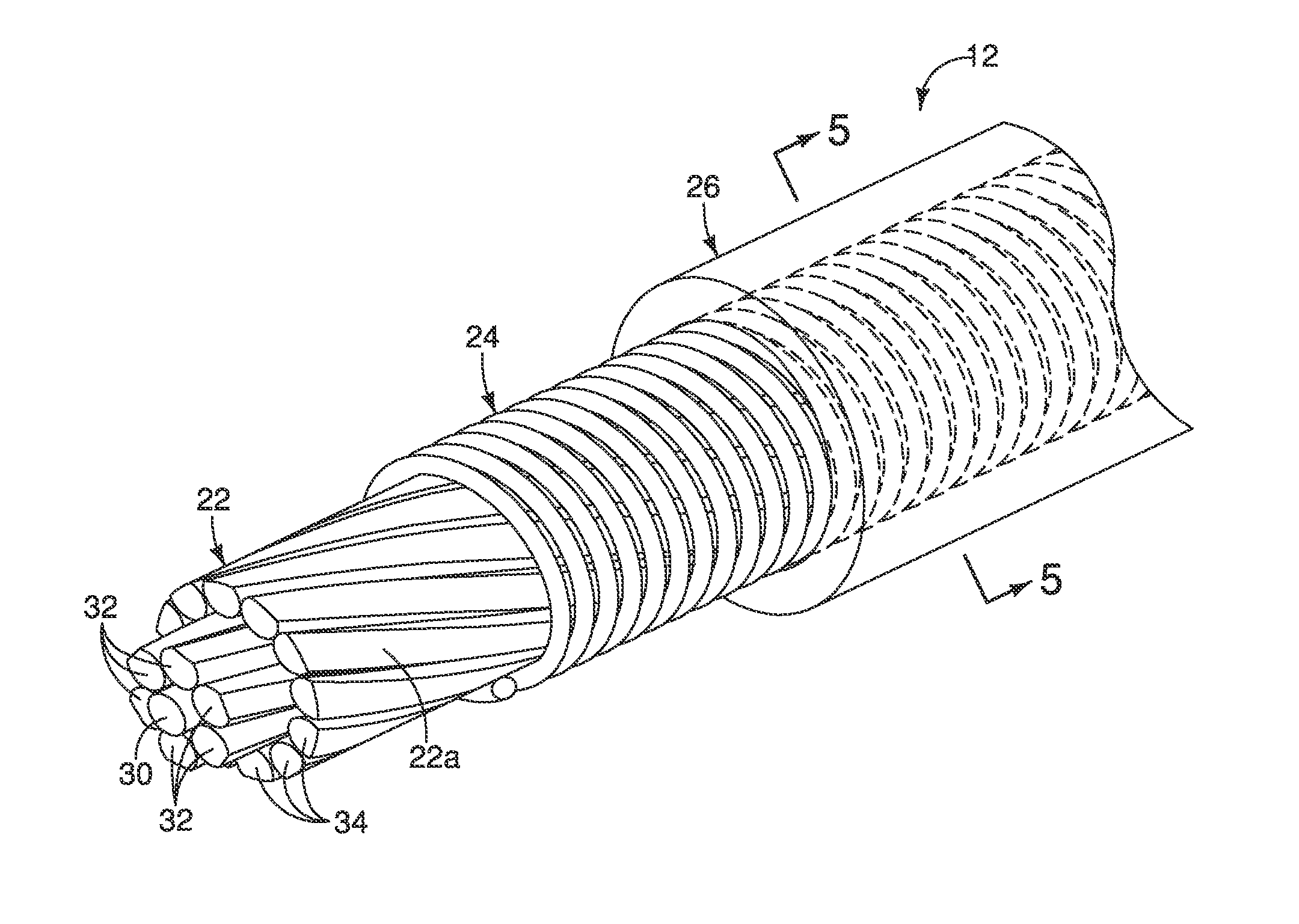
[0045]Referring now to FIG. 12, a bicycle control cable 412 will now be explained in accordance with a The bicycle control cable 412 basically, includes a central wire 422 and a radial protrusion 424. The central wire 422 and the radial protrusion 424 form an inner wire. The central wire 422 includes a center metallic strand 430, a plurality of middle metallic strands 432 and a plurality of outer metallic strands 434. An outer case 426 is provided over a majority of the central wire 422 and the radial protrusion 424. The bicycle control cable 412 is identical to the bicycle control cable 12, as described above, except that a coating of grease G is applied over the central wire 422 and the radial protrusion 424 so that the grease G is provided in the pitches of the radial protrusion 424. Since the radial protrusion 424 includes at least one string that is spirally wound around the central wire 422, the radially outermost surface of the central wire 422 is exposed in areas between co...


PUM


Abstract

A bicycle control cable is provided with a central wire and at least one resin string. The at least one string made of resin is spirally wound onto the radially outermost surface in a direction intersecting with a center longitudinal axis of the central wire with a pitch less than or equal to 1 millimeter. The at least one resin string defines a spiral gap between adjacent windings of the at least one resin string. The at least one resin string defines an outer sliding surface for reducing a sliding resistance of the central wire. The central wire and the at least one resin string define an inner wire configured to slidably move in an axial direction with respect to the center longitudinal axis of the central wire within an outer case to operate a bicycle component.

Description

BACKGROUND[0001]1. Field of the Invention[0002]This invention generally relates to a bicycle control cable. More specifically, the present invention relates to an inner wire of a bicycle control cable such as a Bowden cable.[0003]2. Background Information[0004]Bicycles often have components that are manually operated by a bicycle control cable (e.g., a brake cable and a gear shift cable). In particular, the bicycle control cable interconnects a “manually operated part” of bicycle to a “cable operated part” of bicycle. Examples of “manually operated parts” include brake levers and gear shifters. Examples of “cable operated parts” include brake devices and the gear changing devices. Typically, conventional bicycle control cables have, for example, a tubular outer case and an inner wire that can be inserted into and passed through the outer case. This type of bicycle control cable is often called a Bowden type of bicycle control cable. The outer case of a typical Bowden cable has a syn...

Claims


Application Information

Patent Timeline
Patent Type & Authority Applications(United States)
IPC IPC(8): F16C1/20B62M25/02F16C1/24B62L3/00
CPCF16C1/205F16C1/24B62M25/02B62L3/00B62L3/026B62M25/04B60T11/046D07B5/005D07B2201/2002D07B2201/2037F16C1/10F16C1/20F16C2326/20F16C2326/28Y10T74/20456
Inventor NISHIMURA, ATSUHIROOSE, KENJIASAKAWA, TAKAMOTO
Owner SHIMANO INC
Why Eureka
Try Eureka