Method for determining the position of a rotor of a polyphase motor

a polyphase motor and rotor technology, applied in the direction of electric digital data processing, control systems, instruments, etc., can solve the problems of inability to precisely determine the voltage applied to the system, the current cannot be measured precisely enough to determine the applied waveform in all situations, and the impact of the inverter distortion on the current waveform at standstill and at very low speed

Active Publication Date: 2015-09-24
MAXON MOTOR AG
View PDF13 Cites 21 Cited by
  • Summary
  • Abstract
  • Description
  • Claims
  • Application Information

AI Technical Summary

Benefits of technology

[0030]The object of the present invention is to present a method of the generic kind that

Problems solved by technology

The first problem arises from the impact of the inverter distortion on the current waveforms at standstill and at very low speed.
For this reason, it is difficult to precisely determine the voltage applied to the system.
The interlock time is usually relatively well known but the current cannot be measured precisely enough to determine the applied waveforms in a

Method used


Image

  • Method for determining the position of a rotor of a polyphase motor
  • Method for determining the position of a rotor of a polyphase motor
  • Method for determining the position of a rotor of a polyphase motor

Examples


Embodiment Construction

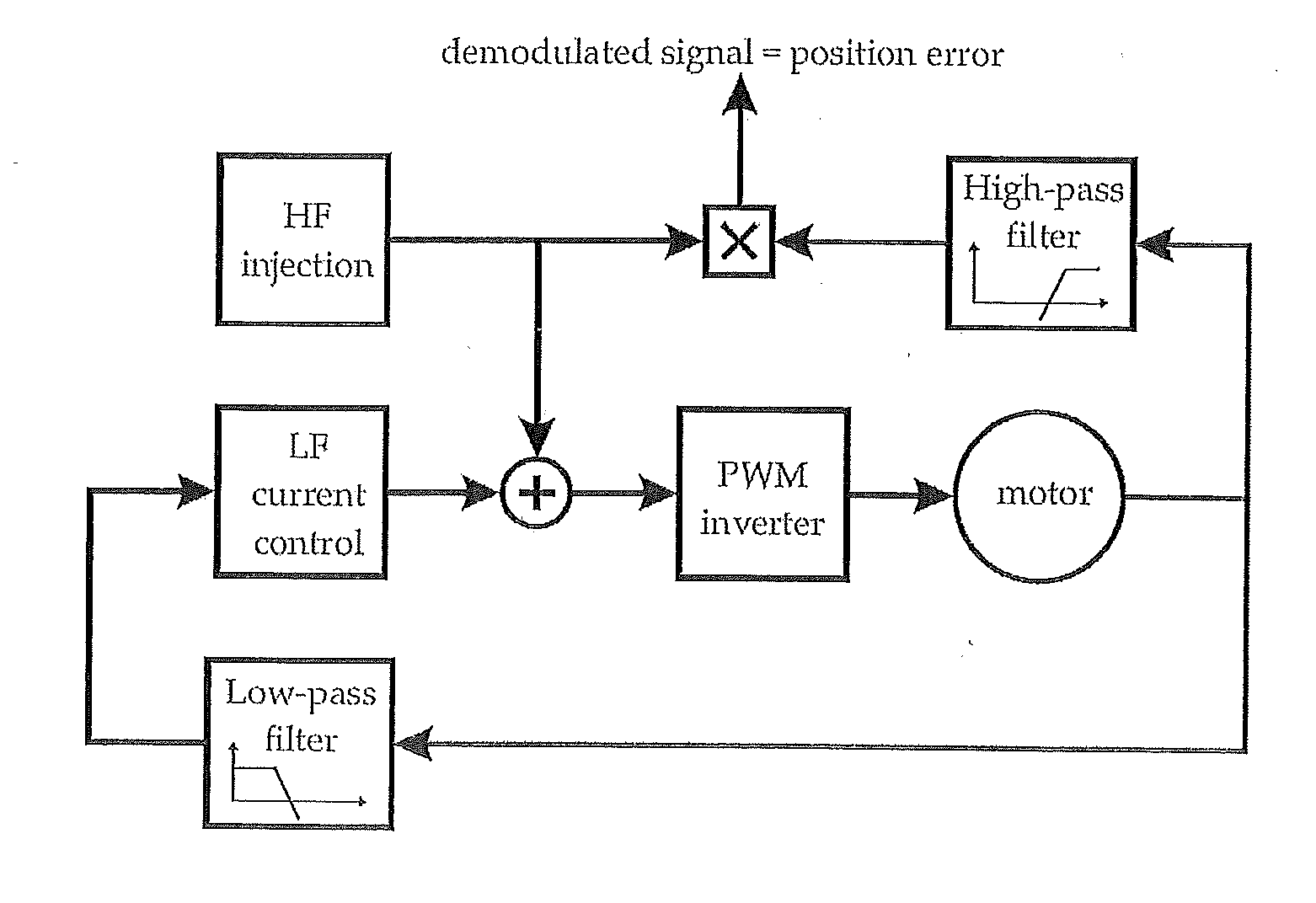
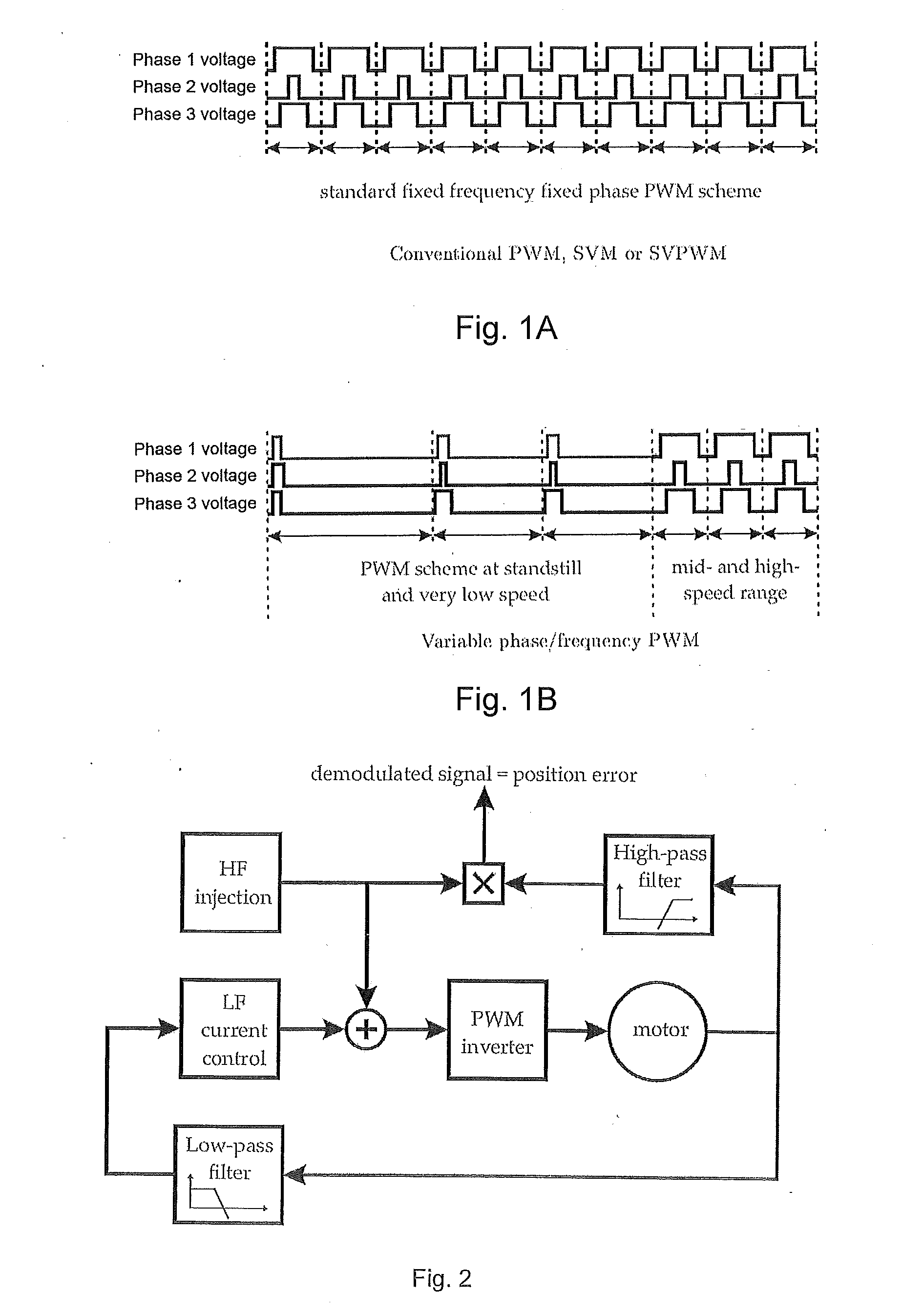
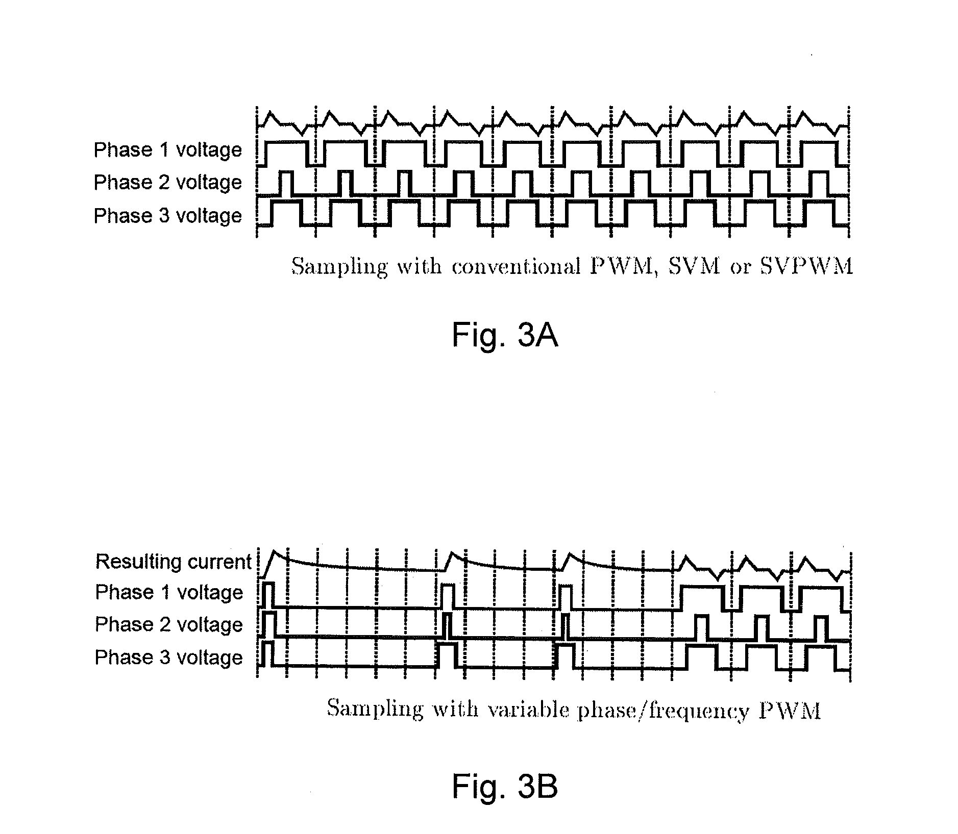
[0030]The object of the present invention is to present a method of the generic kind that allows a precise determination of the rotor position at standstill and / or very low speeds.

[0031]The object is solved by the features of independent claim 1. According to the invention, determination of the rotor position is based on current values measured during a period where zero voltage is applied to the respective phases. The invention has the advantage that a mathematical model of the motor is simplified because terms comprising the voltage can be neglected. Furthermore, the invention allows that determination of the rotor position be based on the identification of the matrix of system time constants. The invention presents a solution to eliminate nearly totally the impact of the inverter distortion and thus to obtain very accurate estimate of the position.

[0032]Within the meaning of the present invention, the term “applying voltage to phases of the motor” also applies if a voltage is act...


PUM


Abstract

The present disclosure relates to a method for determining the position of a rotor of a polyphase motor, e.g., the rotor angle, particularly at standstill. The method can include: applying voltage to phases of the motor, measuring a current in the phases, and determining the rotor position based on the measured current. According to the present disclosure, determination of the rotor position can be based on current values measured during a period where zero voltage is applied to the respective phases.

Description

[0001]The present invention relates to a method for determining the position of a rotor of a polyphase motor, i.e. the rotor angle, particularly at standstill. The method comprising the following steps:[0002]applying voltage to phases of the motor,[0003]measuring a current in the phases, and[0004]determining the rotor position based on the measured current.[0005]Methods of the aforementioned type are well known from the prior art.1 INTRODUCTION[0006]Field oriented control is probably the most effective control technique for obtaining high dynamic performance AC electric drives. Using advanced control techniques with field oriented control allows to achieve a performance close to the machine theoretical limitations. In that case, the performance is mainly limited by the accuracy of the flux orientation estimate. In synchronous drives, the flux position is directly linked to the rotor mechanical position and a position encoder is often used for determining the flux orientation. Encode...

Claims


Application Information

Patent Timeline
IPC IPC(8): G01R25/00G01D5/14
CPCG01D5/14G01R25/00H02P6/183H02P6/185H02P2203/01H02P2203/03
Inventor MARIETHOZ, JEAN-SEBASTIENSCHULTES, OLIVERTANASKOVIC, MARKOFRICK, DAMIAN
Owner MAXON MOTOR AG
Why Eureka
Try Eureka