Endoscope system, operation method for endoscope system, processor device, and operation method for processor device

a technology of endoscope and operation method, which is applied in the field of endoscope system, operation method of endoscope system, and operation method of processor device, which can solve the problem of few diagnostic materials compared with real-time diagnosis

Active Publication Date: 2015-10-01
FUJIFILM CORP
View PDF7 Cites 15 Cited by
  • Summary
  • Abstract
  • Description
  • Claims
  • Application Information

AI Technical Summary

Benefits of technology

[0014]It is preferable to further include a focus detection unit that detects a focus of an image to be acquired. Preferably, the control unit performs control to acquire the first still image when an operation of increasing the imaging magnification using the imaging magnification change operation unit is detected and to acquire the second still image when the focus detection unit detects that the image is in focus after acquisition of the first still image.
[0015]Preferably, the control unit performs control to acquire the first still image when an operation of reducing the imaging magnification using the imaging magnification change operation unit is detected and to acquire the second still image when an operation end of the imaging magnification change operation unit is detected after acquisition of the first still image.
[0016]It is preferable to further include an imaging optical system capable of changing an imaging magnification of the observation target; an imaging magnification change operation unit for inputting an imaging magnification change instruction to change the imaging magnification to the imaging optical system; and a control unit that performs control to acquire the first still image and start acquisition of the video based on the imaging magnification change instruction and to end the acquisition of the video when an operation end of the imaging magnification change operation unit is detected.
[0017]Preferably, a first mode and a second mode different from the first mode are prepared as modes for acquiring the first still image and the video or the second still image, and the control unit performs control to acquire the first still image in one of the first and second modes and then start acquisition of the video by switching the one mode to the other mode.
[0018]It is preferable to further include a display control unit that displays a plurality of the first still images stored in the storage unit side by side on a monitor and a selection unit for selecting the plurality of first still images displayed side by side on the monitor. Preferably, when the video associated with the first still images is stored in the storage unit, the display control unit displays the first still image selected by the selection unit on the monitor in an enlarged manner and reproduces the video, which is associated with the selected first still image, on the monitor.
[0019]It is preferable to further include a display control unit that displays a plurality of the first still images stored in the storage unit side by side on a monitor and a selection unit for selecting the plurality of first still images displayed side by side on the monitor. Preferably, when the second still image associated with the first still images is stored in the storage unit, the display control unit displays the first still image selected by the selection unit on the monitor in an enlarged manner and reproduces the second still image, which is associated with the selected first still image, on the monitor.

Problems solved by technology

Therefore, there are few diagnostic materials compared with real-time diagnosis in which diagnosis can be performed while changing the observation conditions arbitrarily.

Method used


Image

  • Endoscope system, operation method for endoscope system, processor device, and operation method for processor device
  • Endoscope system, operation method for endoscope system, processor device, and operation method for processor device
  • Endoscope system, operation method for endoscope system, processor device, and operation method for processor device

Examples


first embodiment

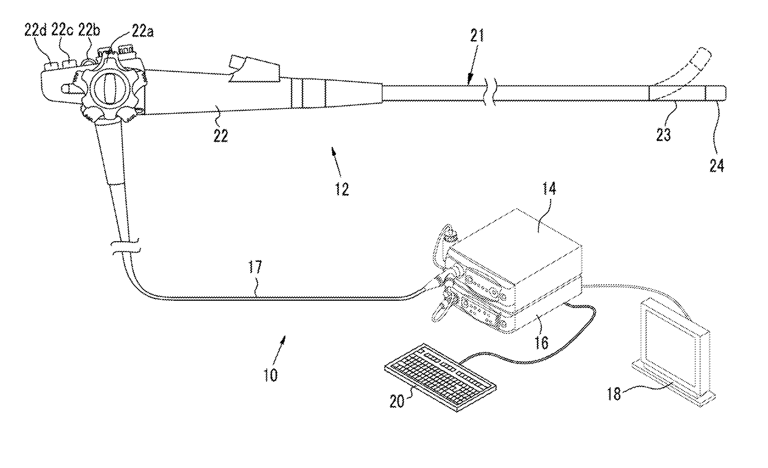
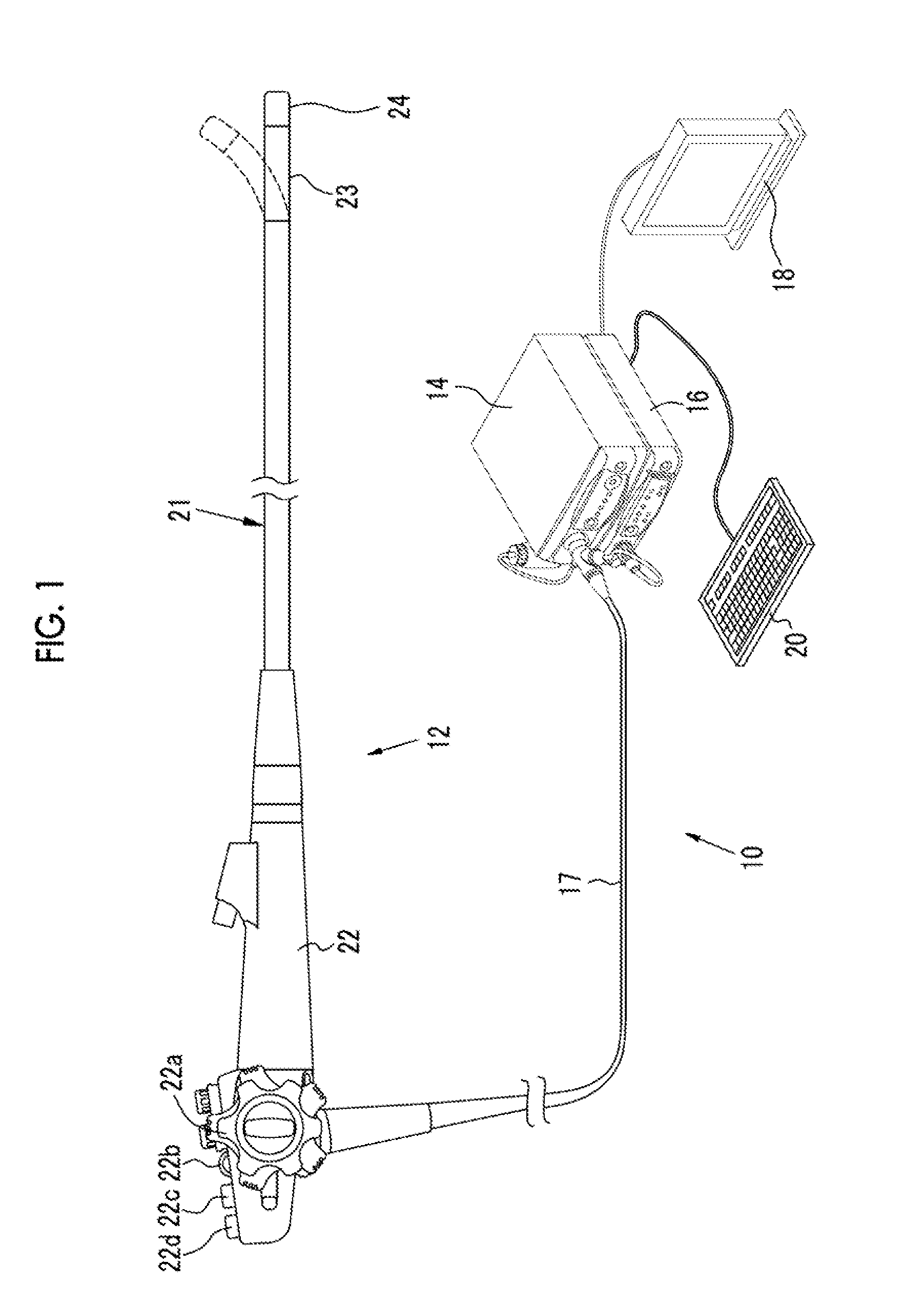
[0048]As shown in FIG. 1, an endoscope system 10 includes an endoscope 12, a light source device 14, a processor device 16, a monitor 18, and a console 20. The endoscope 12 is optically connected to the light source device 14, and is electrically connected to the processor device 16. The endoscope 12 includes an insertion unit 21 that is inserted into a subject, an operating unit 22 provided at the proximal end of the insertion unit 21, and a bending portion 23 and a distal portion 24 that are provided at the distal side of the insertion unit 21. By operating an angle knob 22a of the operating unit 22, the bending portion 23 is bent. The distal portion 24 can be directed in a desired direction by the bending operation.

[0049]In addition to the angle knob 22a, a freeze button 22b, a zoom operation unit 22c, a mode selector SW (mode selector switch) 22d, and the like are provided in the operating unit 22. The freeze button 22b is a first still image acquisition operation unit for input...

second embodiment

[0086]As shown in FIG. 13, in an endoscope system 200 according to a second embodiment, a focus detection unit 201 is added to the endoscope system 10 according to the first embodiment. In addition, instead of the imaging control unit 65, an imaging control unit 265 that operates based on the imaging magnification change instruction input not only from the freeze button 22b but also from the zoom operation unit 22c is provided in the endoscope system 200 according to the second embodiment. The endoscope system 200 according to the second embodiment is the same as the endoscope system 10 according to the first embodiment except for those described above.

[0087]The focus detection unit 201 acquires a normal observation image or a special observation image from the image generation unit 62, and detects whether or not the image is in focus. When the focus matches predetermined criteria or more, a focus pass signal is input to the imaging control unit 265.

[0088]The operation of the imagin...


PUM


Abstract

The endoscope system includes an image signal acquisition processing unit and an image generation unit that acquire a first still image and a video or a second still image before and after acquisition of the first still image based on an image signal obtained by imaging an observation target using an image sensor, an association unit that associates the first still image with the video or associates the first still image with the second still image, and a storage unit that stores the first still image and the video associated with each other or stores the first still image and the second still image associated with each other.

Description

CROSS-REFERENCE TO RELATED APPLICATIONS[0001]The present application claims priority under 35 U.S.C. §119 to Japanese Patent Application No. 2014-074279, filed Mar. 31, 2014, all of which are hereby expressly incorporated by reference into the present application.BACKGROUND OF THE INVENTION[0002]1. Field of the Invention[0003]The present invention relates to an endoscope system for imaging an observation target in a subject, an operation method for an endoscope system, a processor device, and an operation method for a processor device.[0004]2. Description of the Related Art[0005]In the medical field, it is common to perform diagnosis by observing an image obtained by imaging an observation target (mucous membrane of the digestive tract or the like) in a subject using an endoscope system. The endoscope system includes a light source device that generates illumination light for irradiating an observation target, an endoscope that has an insertion unit inserted into the subject and ima...

Claims


Application Information

Patent Timeline
Patent Type & Authority Applications(United States)
IPC IPC(8): A61B1/045A61B1/00H04N5/232G16H30/20
CPCA61B1/045H04N5/23212A61B1/0005H04N5/23245A61B1/00009H04N5/23296A61B1/0002A61B1/00188A61B1/0638A61B1/0653G16H30/20A61B1/000094A61B1/0655H04N23/67H04N23/125H04N23/69H04N23/667
Inventor SHIGETA, NORIMASA
Owner FUJIFILM CORP
Why Eureka
Try Eureka