
Device for Automatically Drilling Wheel Rim Online

a technology of automatic drilling and wheel rim, which is applied in the field of drill bits, can solve the problems of frequent breakage of drill bits, high labor intensity, and low efficiency, and achieve the effect of prolonging the service life of drill bits

Inactive Publication Date: 2015-10-01
CITIC DICASTAL
View PDF5 Cites 18 Cited by
  • Summary
  • Abstract
  • Description
  • Claims
  • Application Information

AI Technical Summary

Benefits of technology

The present invention is an automatic wheel rim drilling device that can online drill rims, prolong the life of drill bits, and improve efficiency. The device includes a drill bush, upper and lower guide posts, upper and lower sliding sleeves, upper and lower pressing plates, a drilling power head, and a bracket. The bracket is connected to a support platform fixed on the frame and a servo electric cylinder is mounted on the platform for feed movement. The device can automatically drill X-ray rejects of wheels, adapt to flow casting spun blanks with thick rims, avoid drill bit breaks, and has high degree of automation, advanced process, safe and stable performance, and wide application range.

Problems solved by technology

In a traditional method of drilling, the wheels are drilled one by one by a worker with an electric hand drill, with high labor intensity and low efficiency; although automatic drilling devices are also designed by many enterprises, a drill bit cannot be positioned at all due to an arc surface of the outer side of the wheel rim during drilling, and therefore the drill bit is frequently broken.

Method used


Image

  • Device for Automatically Drilling Wheel Rim Online
  • Device for Automatically Drilling Wheel Rim Online
  • Device for Automatically Drilling Wheel Rim Online

Examples


Embodiment Construction

[0013]Details and operation of the specific device provided by the invention will be described below in conjunction with the accompanying drawings.

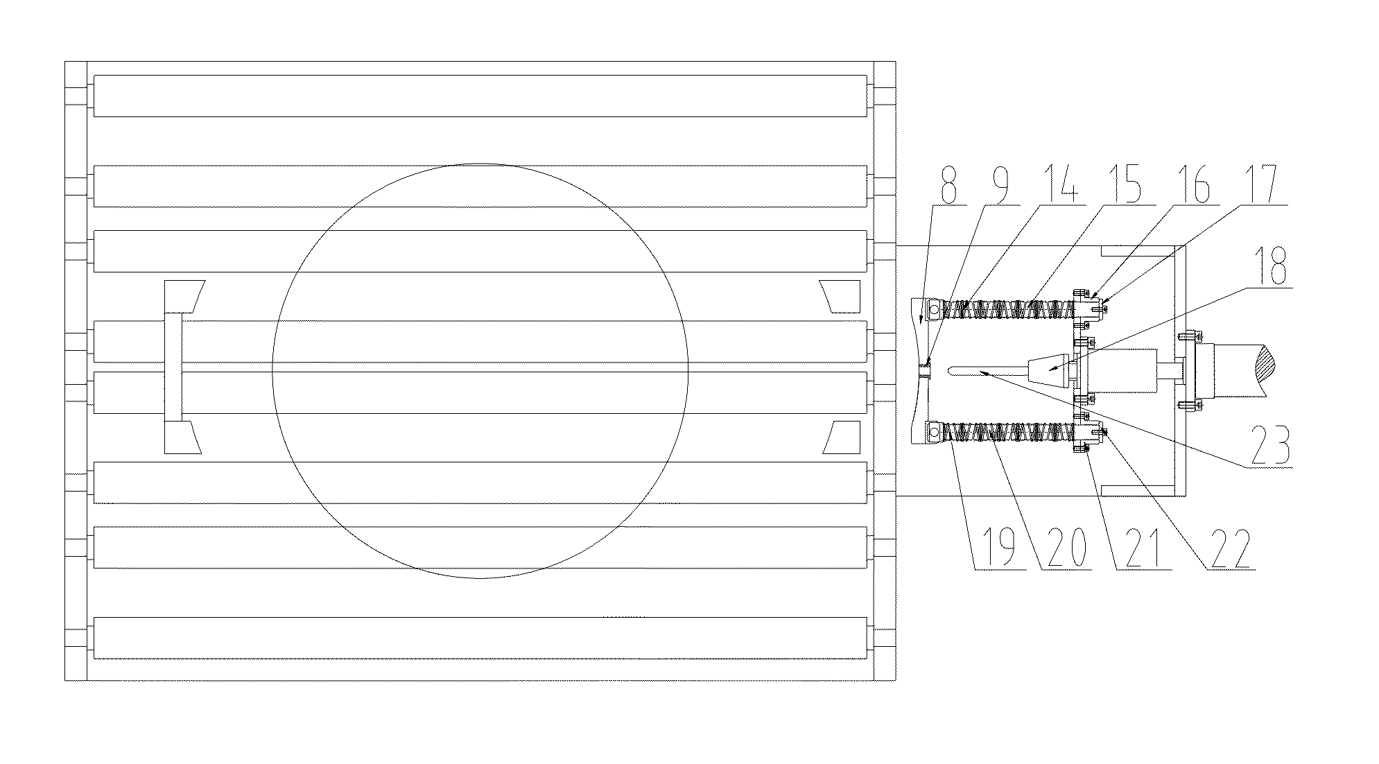
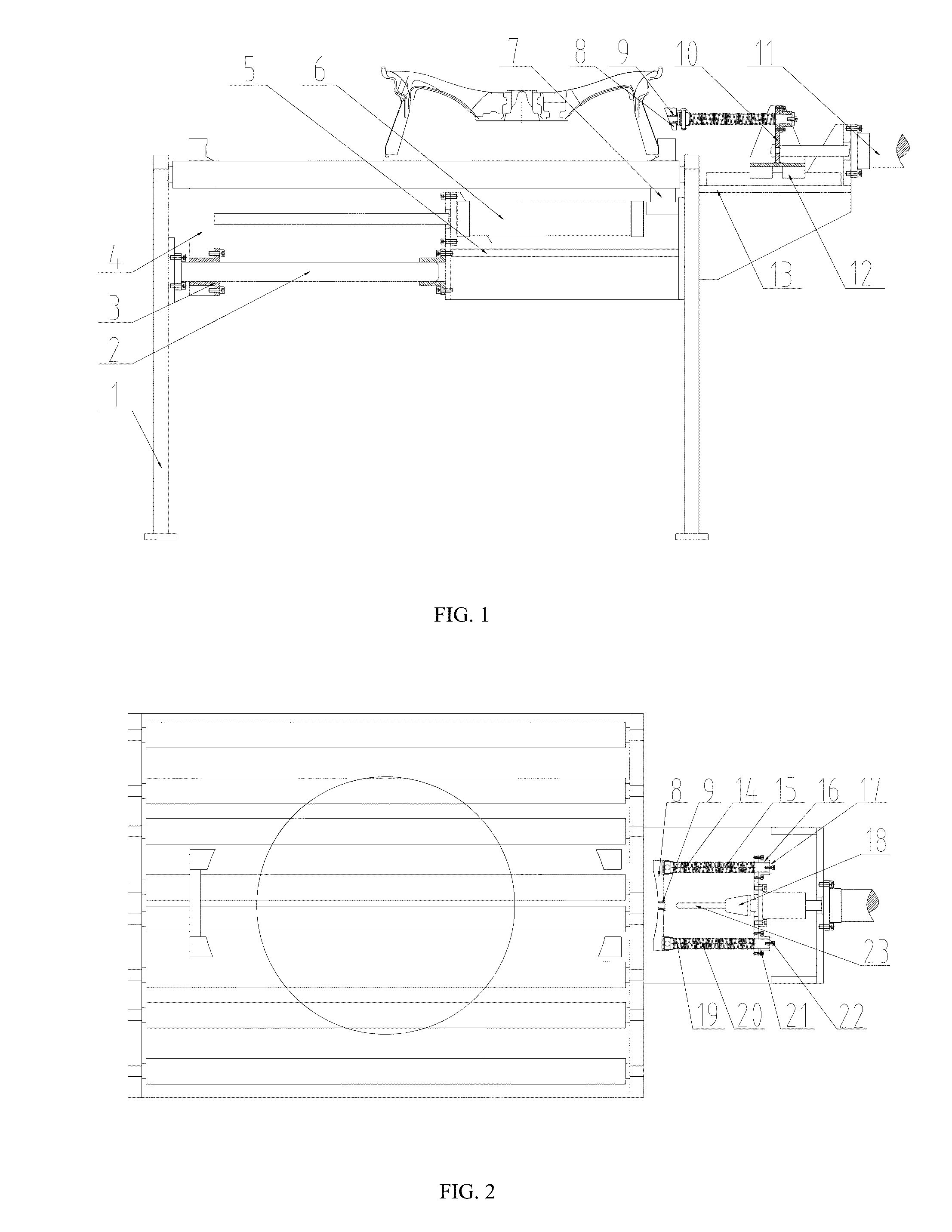
[0014]The device comprises a frame 1, guide rods 2, guide sleeves 3, left clamping blocks 4, a lower supporting plate 5, an air cylinder 6, a right clamping block 7, a profiling drill jig 8, a drill bush 9, a bracket 10, a servo electric cylinder 11, a guide rail 12, a support platform 13, an upper spring 14, an upper guide post 15, an upper sliding sleeve 16, an upper pressing plate 17, a drilling power head 18, a lower spring 19, a lower guide post 20, a lower sliding sleeve 21, a lower pressing plate 22 and a drill bit 23. The two guide rods 2 are fixed under the frame 1, and the two guide sleeves 3 cooperating with the guide rods 2 are mounted below the two left clamping blocks 4; the air cylinder 6 is fixed above the lower supporting plate 5, and an output rod of the air cylinder 6 is connected with a middle connecting part between t...


PUM


Abstract

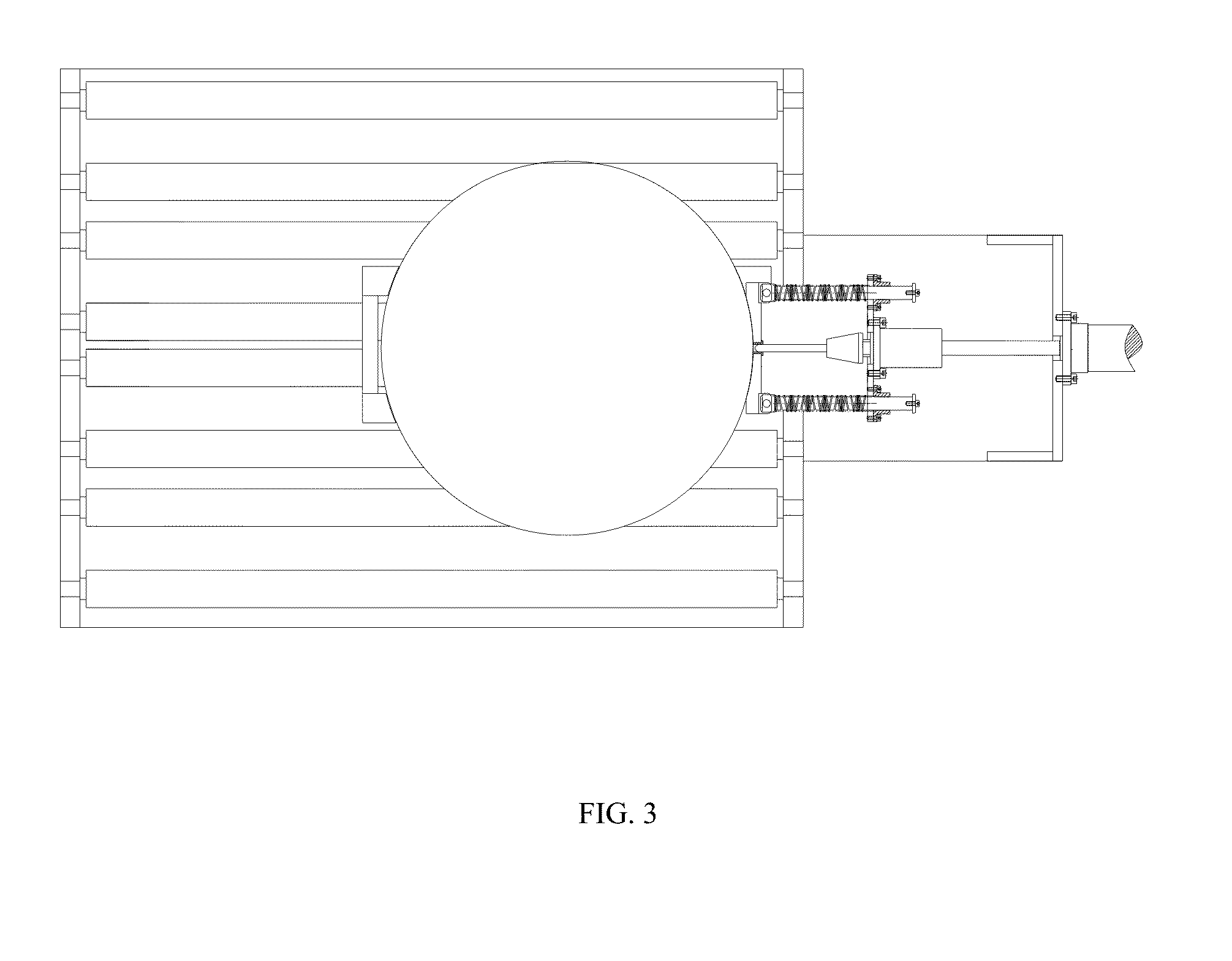
The present invention provides an automatic wheel rim online drilling device, comprising a frame, an air cylinder, a profiling drill jig, a drill bush, a servo electric cylinder, a drilling power head, etc. Firstly, a sensor enables a wheel to be positioned, and the air cylinder causes left clamping blocks to move rightward by two guide rods and guide sleeves so as to clamp the wheel jointly with a right clamping block; the servo electric cylinder causes a drilling system to move toward the wheel and the profiling drill jig can first come into good contact with the wheel rim and then the servo electric cylinder moves continuously to compress upper and lower springs so that the drill bit enters the drill bush, and at this time the drilling power head drives the drill bit to rotate, thus starting drilling on the wheel rim. By using the device of the present invention, X-ray rejects of wheels can be automatically marked by drilling, and the device can adapt to flow casting spun blanks with thick rims; and through orientation of the drill bush, the situation that the drill bit is frequently broken when drilling on the arc surface of the outer side of the wheel rim can be effectively avoided.

Description

TECHNICAL FIELD[0001]The present invention relates to a drilling device, in particular to a drilling device for a circumferential object surface.BACKGROUND ART[0002]During manufacturing of aluminum alloy wheels, to avoid potential safety risk due to loss of X-ray rejects, traditionally X-ray rejected products are drilled in the wheel rims so as to be accurately determined as rejects in subsequent airtight testing. In a traditional method of drilling, the wheels are drilled one by one by a worker with an electric hand drill, with high labor intensity and low efficiency; although automatic drilling devices are also designed by many enterprises, a drill bit cannot be positioned at all due to an arc surface of the outer side of the wheel rim during drilling, and therefore the drill bit is frequently broken. By adopting the device in the present invention, the above problems can be totally avoided while the production efficiency is improved, and the device can adapt to workpieces with th...

Claims


Application Information

Patent Timeline
Patent Type & Authority Applications(United States)
IPC IPC(8): B23B47/28B23B41/00
CPCB23B47/281B23B2222/04B23B2215/08B23B41/00Y10T408/56245
Inventor XUE, BOWENGUO, JIANDONGLIU, WEIDONGREN, CHANGJIUWANG, YONGNINGZHU, ZHIHUALI, CHANGHAI
Owner CITIC DICASTAL
Learn More